The Control Techniques Drives and Controls Handbook

This handbook contains technical information for practicing drive and electrical engineers, covering the technology underlying drives, motors, and control units and modern practical applications.
Many applications exist where something has to be controlled to follow a reference quantity. For example, the speed of a large motor may be set from a low-power control signal. This can be done using a variable-speed drive as shown in Figure 4.1.
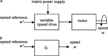
Ideally, the relationship between the reference and the motor speed should be linear and the control system should respond instantly to changes in the reference. Any control system can be represented, as shown in Figure 4.1 b, with an input reference signal, in this case a speed reference, a transfer function G and an output, in this case the speed of rotation of the motor shaft W. For the system to be ideal, the transfer function G would be a simple constant, so that the output is proportional to the reference with no delay.
Unfortunately, the transfer function of many systems is not a constant and so, without any form of feedback from the output to correct for the nonideal nature of the transfer function, the output does not remain proportional to the control signal. Using an induction motor supplied by a simple open-loop variable-speed drive as an example, the following are some unwanted effects that can occur in control systems.
Regulation
The output of a simple open-loop drive can be a fixed frequency, which is proportional to the speed demand signal. Therefore, the frequency applied to the motor remains...