VSWR Explained
Featured Product from A.H. Systems Inc.
Download this article of VSWR Explained
Here is a useful "cheat sheet" converting VSWR to the percentage of reflected power.
This online VSWR Calculator is also very useful
VSWR Explained
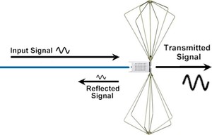
VSWR Stands for 'Voltage Standing Wave Ratio' and is used in EMC to specify the effect of a mismatch presented to a test system signal.
Brief History of VSWR
When electric telegraphy was the dominant means of wired communication, the lines used were comprised of bare copper wires suspended on telegraph poles. For insulation the line relied on the large spacing between the wires as well as the wires being mounted on individual glass or ceramic stand-offs. These lines ran for miles and miles and were prone to damage caused by storms, fallen trees, and partial shorts due to the top of the poles making good nesting sites for large birds.
The lineman sent to locate and correct the fault somewhere along the miles of suspended wires could at least identify the type of fault by examining the standing wave on the line created by the fault.
The lineman would gauge how brightly a light bulb connected across the line would glow as the connection was moved along the line. If the bulb lit brightly at one place on the line and would not light at all further along the line, then he knew to look along the line for an open or short circuit. If the bulb was fairly bright at one place and somewhat dimmer in another, he knew to look for a partial short across the wires.
This all seems rather primitive, but we should bear in mind that voltage measuring instruments of the day were a delicate mechanism housed in hand-made wooden cases. This made them expensive and fragile, whereas the light bulb was comparatively cheap and robust. The method was cleverer than you might at first suppose, since it was a form of bolometer able to indicate the RMS value of the two voltage extremes on the line.
Commonplace but pretty much gone in the RF industry by the 1990s, a bolometer fed with RF would be warmed by the RF resulting in a change in resistance in one arm of a bridge. The output of the bridge gave the RMS value of the RF waveform, no matter how complex the waveform.
At microwave frequencies slotted lines became a way of accurately determining the ratio of the maximum voltage to the minimum voltage (the VSWR, symbol 's'), and because of the simplicity of measurement and the easy math associated with it, VSWR became an everyday parameter. As the name suggests, a slotted line is a length of waveguide with a slot along the top. A probe is moved along the slot and a detector gives the voltage at any point on the line. Once you have obtained the two extremes of voltage you can determine the ratio of the two. Once you have this ratio it is easy to calculate the reflected power coefficient, symbol rho. The reflected power coefficient is the amount of power reflected back compared to the incident power. The AH website has a calculator allowing conversion between s and rho.
What is VSWR
We continue the explanation by ignoring the Voltage and Ratio parts for now and examine how a Standing Wave is created.
The Standing Wave
Unless a test signal on a transmission line (e.g. 50 ohm coaxial cable) is terminated in 50 ohms, some of the signal will be reflected back along the line. This can best be understood by looking at the extreme mismatch termination values, that is a short circuit (zero ohms) and an open circuit (infinite ohms).
Short-Circuit Termination
A voltage cannot exist across a perfect short-circuit, that is the voltage can only have the value 0 volts at the short-circuit. A basic law of physics is the conservation of energy. Energy cannot just disappear, it has to accounted for somehow. Mother Nature gets around the zero volts requirement by creating an equal and opposite signal that travels back down the line. At the short-circuit the +E and -E cancel each other to give the required zero volts.
Open-Circuit Termination
This is the 'dual' of the short-circuit situation. A current cannot flow in a perfect open-circuit, that is the current can only be zero amps at the open-circuit. Again, Mother Nature gets around the zero amps requirement by creating an equal and opposite signal that travels back down the line. At the open-circuit the +I and -I cancel to give the required zero amps. Technically this should be +H field and -H field, but for our purposes we will stick with +I and -I.
At last the acronym Voltage Standing Wave Ratio makes sense.
Welcome to A.H. Systems, inc.
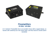
A.H. Systems has been established since 1974 and manufactures a complete line of affordable, reliable, EMI test equipment. Our individually calibrated EMI Test Antennas, Preamplifiers, Current Probes and Low-Loss Cables satisfy many test standards including CISPR, MIL-STD, FCC, EN, VDE, IEC and SAE. With a wide variety of mounting configurations, we can also offer tripods and accessories that compliment other EMI testing equipment used to complete your testing requirements. We are also committed to providing all of our clients with no cost prompt and professional technical support. Manufacturing high quality products at competitive prices with immediate shipment plus prompt technical support are our goals to improve the quality of your testing requirements.
Here is a pdf version of our product catalog.