Robotic Deburring Tools Information
 In metal working and metal forming, it is common to have excess material protruding or sticking out from the manufactured part. This excess metal is referred to as a burr in metal turning, milling, stamping, and other cutting operations. Common factors such as dull cutting tools, improper feed rate, poor machine-ability of the metal, etc. are the main sources of “burrs.” Being that these burrs are metal, they can create problems from dangerous sharp edges that are hazardous to handlers and create assembly fit issues and broken burr damage problems. When casting metal components, the “parting line” is where two halves of the mold come together. It is at this interface that flashing often occurs (called parting line flash) when a small amount of molten metal leaks out of the mold. This PLF also presents potential problems in that these often sharp features can lead to serious cuts and lacerations to persons handling the part and other process issues.
Types of Robotic Deburring Tools
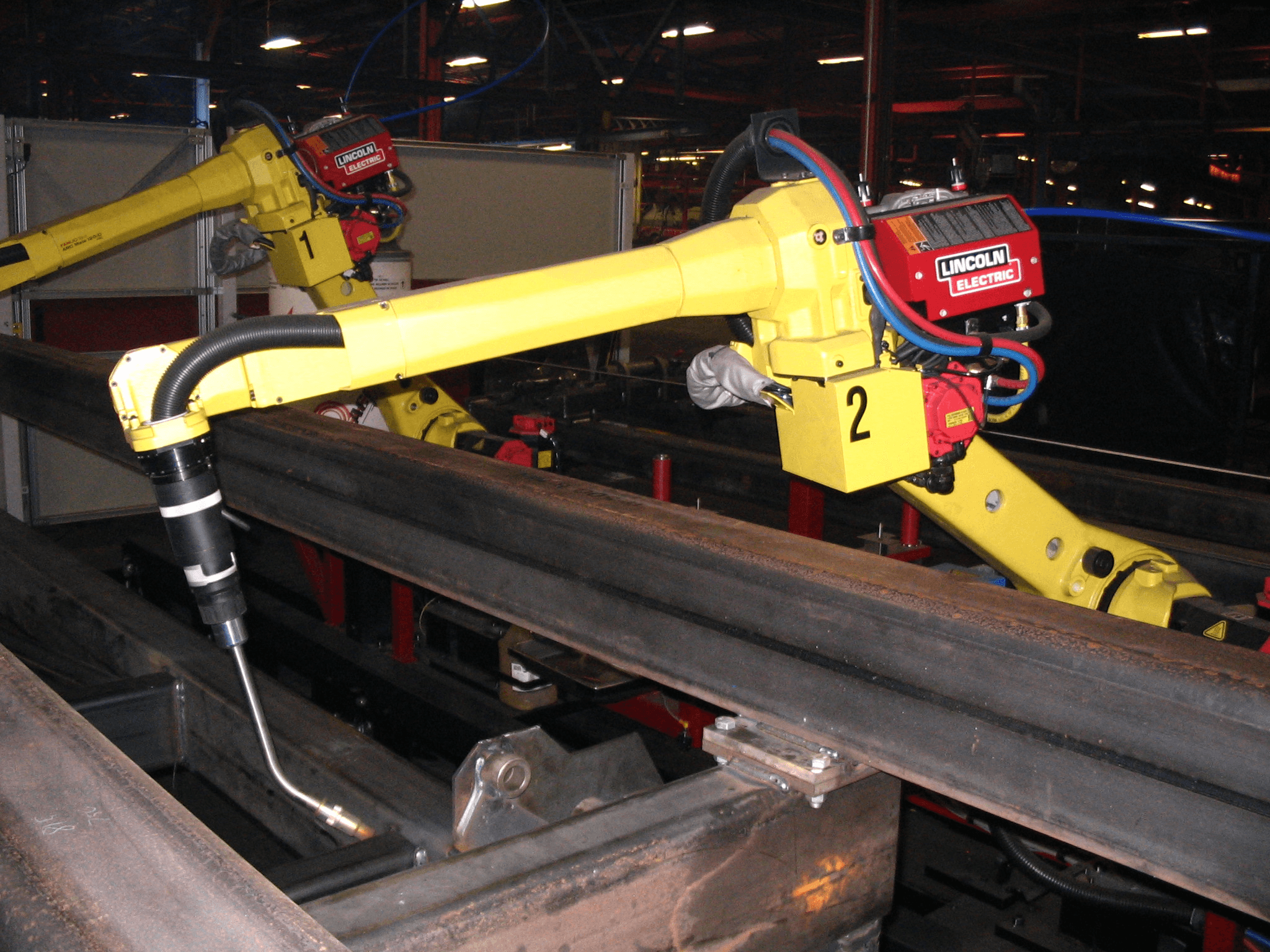
Manual deburring has been the tedious process of cleaning up these parts used for hundreds of years. In recent times, potential health and safety issues sometimes associated with manual deburring operations and advances in automated systems has led many manufacturers to turn to automated, robotic deburring methods. The typical robot used for deburring purposed is the “arm” or articulating robot. This robot design features rotary joints and can range from simple two joint structures to 10 or more joints. The arm is connected to the base with a twisting joint. The links in the arm are connected by rotary joints. Each joint is called an axis and provides an additional range of motion. Industrial robots commonly have four or six axes. End-effectors are replaceable/interchangeable tools that are mounted at the end of the arm that does the work. Robotic deburring tools are robotic end-effectors for removing burrs, flashing, and other unwanted edge properties caused by cutting, molding, or machining. They are driven by electric, pneumatic, or hydraulic power and feature a straight, angled, or multiple-position head that accepts the rotating deburring tools.
An inherent feature of robotic deburring tools is called “compliance.” While spinning at high speeds, a rotary cutting de-burr or file rides on a cushion of air that provides a reliable field of compliance while maintaining a constant force. This field of compliance provides a high degree of stiffness in the path direction and a low degree of stiffness in the contact direction. There are two types of compliance seen in robotic de-burring tools.
Radially-compliant deburring tools are often turbine-driven units for deburring a variety of materials with a robot or CNC machine. These tools offer resistance in a direction in line with the axis of the tool. Radially-compliant deburring tools are well-suited for the removal of parting lines or flash from parts.
Axially-compliant deburring tools are stiff in the radial direction of the tool, perpendicular to the axis and compliant along the axis of the tool. Axial-compliant deburring tools utilize a vane-type motor and a floating rotary cutting file for edge deburring and chamfering of parts.
Specifications
Selecting robotic deburring tools requires an analysis of performance specifications, mounting styles, cutting tools, and product applications. Performance specifications include:
- operating speed
- idle speed
- torque
- power
- Z-axis compliance
Idle speed and operating speed are usually measured in revolutions per minute (rpm). Torque is typically measured in inch-pounds (in-lbs) or feet-pounds (ft-lbs). Power is frequently measured in horsepower (hp). Z-axis is expressed in inches (in.). Products that are specified in metric units such as millimeters (mm) are also available. In terms of mounting styles, some robotic deburring tools are designed to fit robotic wrists or tool holders on CNC machines. Others mount on benches, assembly lines, or overhead gantries. The inherent compliance at the deburring tip saves robot programming time. Programmers can program fewer path points since the tool compliance will accommodate deviations between the robot path and the part profile. The robot path does not have to precisely follow the part edge. Programming savings are multiplied in applications where multiple passes are necessary for achieving a desired finish.
Programming the robot path is achieved by temporarily mounting a dowel pin of the same diameter as the cutting tool in the spindle. The robot is then moved to a point where the dowel touches the edge of a finished workpiece and the point is recorded. This process is repeated at intervals along the edge of the part. A small tool offset is then programmed into the robot controller to account for part profile variations.
Related Information
Engineering360—Norton Red Heat R983 Belts and Discs: Premium Metalworking Tools
Image credit:
Phasmatisnox / CC BY-SA 3.0
