How Connections Impact Testing
Featured Product from A.H. Systems Inc.

Connections in RF testing
Almost every RF test setup requires connectors and cables. Connectors will influence test results in various and sometimes unpredictable ways. Test equipment can compensate for some of these influences but often with detrimental effects. Knowing how the connections used in a test setup will affect test results is important to create a valid test environment.
Connector and cable options
In RF testing there are various components, such as the antenna, testing equipment like a network analyzer, device under test and cables, connectors and adapters. In this setup, there are many options for the type of connectors as well as the type of coax and configurations. The best setup would have the lowest attenuation across all frequencies and provide high accuracy results. While the ideal setup is often not possible, many options exist to get close. One option is to use fewer connectors with the highest quality and shortest length of coax. This may require custom coax with the correct connectors on each end. Due to the flexible nature of testing equipment, the coax and connectors in a test setup are often a secondary consideration. Adapters such as gender changes and coax cables that are longer than required are often used. It is important to understand how these equipment choices will influence a test and if those influences are acceptable. Consequently, the connections should be given great consideration.
Types of connectors and coax
Many different kinds of RF connectors exist and each has its own characteristics of frequency range, decibels of loss and power, as well as other aspects. BNC (Bayonet Neill-Concelman) connectors are easy to connect due to a twist-lock system. These connectors work well up to about 4 GHz and 70 W power and are standard on test equipment. N connectors are one of the most commonly used for frequencies up to 11 GHz. They also have a high power range, around 150 W, where precision N is good up to 18 GHz and 250 W. Subminiature version A (SMA) connectors work for frequencies up to 26.5 GHz and 70 W, but also have other variations. The small size and high frequency range make them useful for many applications. For instance, 3.5 mm and 2.9 mm will mechanically mate with an SMA connector but with a different diameter corresponding to the size. They also both offer a higher frequency range than SMA, where 3.5 mm typically works up to 34 GHz and 45 W, and 2.9 mm works up to 40 GHz and 20 W. Another smaller connector option is 2.4 mm, which has a frequency range up to 50 GHz and power of about 15 W. On the other end of the size spectrum, 7/16 DIN utilizes a measurement of 7 mm for the inner contact with the outer contact having a 16 mm diameter. This is a larger connector compared to the others, but it is popular in high-power uses. This connector goes up to about 7.5 GHz and 820 W.
In addition to connectors, different types of coax options also exist. RG58 is used for low-power signals up to about 1 GHz, and it is often used with BNC and other connectors. RG142 is a double-shielded, 50-ohm impedance cable with an upper frequency range of 8 GHz. RG214 also has a double shield and a typical upper frequency range of 4 GHz. Finally, RG223 is a 50-ohm cable that works up to 12.4 GHz and has some of the lowest loss in the standard cable. Lower-loss, higher-frequency range cables are also available. Cables such as SAC-18G-X or SAC-40G-X have power ratings up to 1,900 W at 1 GHz and have frequency ranges up to 40 GHz at low power ratings.
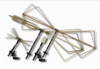
A.H. Systems makes all cables in custom lengths depending on the test setup. Low-loss cables are useful when a more accurate test is required and are a good option in general. The combination of various cables and adapters will achieve varying degrees of attenuation, depending on the test requirements.
Gender and connector adapters
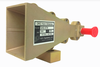
When testing RF, it is often the case that the connectors on various test equipment and the antenna are not the same type or are the incompatible gender. A common way to deal with this mismatch is to use adapters. Some adapters simply change the connector gender, while others convert between two different connectors. While utilizing adapters often creates a functioning test, they can also have a detrimental impact. Each adapter and connector introduces some attenuation. While this attenuation is calibrated out, it will negatively influence the test. Attenuation is not typically flat across frequencies; it will influence a test in other ways such as by decreasing the dynamic range and test accuracy.
Custom cables
Creating custom cables with the connectors to match the mating equipment is an alternate way of adapting when different connector types or genders are required. The fewer connectors and adapters, the less attenuation and impact on a test. Additionally, the high-frequency and power rated connectors and cable will provide for data that is more detailed. If the equipment performs the same test many times, then ensuring that the correct cables and adapters are available is not that difficult. If the type of test is not consistent, then it will require an assortment of connectors. In this case, other constraints such as time and money will factor more into the test setup where adapters on hand are used instead of custom cables. While this is a viable option, it does have consequences.
Accounting for attenuation
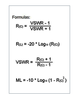
It is possible to account for and calculate what the expected loss from various connector and cable configurations will be. Each connector, adapter and cable will have specifications that document the expected loss at various frequencies. It is possible to arrive at an expected loss for a cable, connector or adapter system. Another way is to measure the loss of a system, which involves transmitting and receiving through a system and then adding the unknown cable and connectors, where the difference equals the loss of the added connections. Often, one connector or cable choice creates a bottleneck that lowers the maximum frequency, power or both. It is important to note the highest frequencies and power that various tests will require, as well as the capabilities of the connections. Other factors such as cable length or any damaged equipment will also play a role in overall attenuation. Online calculators such as this one from A.H. Systems, can help with this calculation.
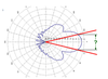
Frequency range vs. attenuation
Attenuation from cables and connectors is rarely flat across the spectrum and is often nonlinear as well. This can make loss difficult to account for as it becomes necessary to know the testing frequencies. If multiple frequencies are going to be used in testing, then understanding how the attenuation will affect each frequency is important. More often, low-frequency tests have less issue with loss than high-frequency tests. Tests that span both low and high frequencies may have more detail in the lower range but less at higher frequencies. In some instances, unusual frequency dips may even occur due to equipment characteristics. Test equipment can often compensate for this unevenness with some compromises. Knowing the spectral response of any given test setup will help understand the results.
Measuring and adjusting for attenuation
While all these different connection aspects in a test make it more complicated, it is not that difficult to measure and adjust for the attenuation of a system, even without a bunch of calculations. Often, various types of measurement equipment can establish a baseline for calibrating the connection factors. Even if the equipment cannot directly account for the attenuation, once the attenuation is measured, the difference between the baseline and test data can be calculated. However, even though the attenuation is accounted for, it does not mean that it will negatively affect the test.
Dynamic range
The availability of different adapters, connectors and cables does not mean that attenuation can be factored into the test and therefore ignored. It may seem like it does not matter what connection options are chosen, so long as the connections are made and the equipment can account for them. Sometimes users will even stack multiple adapters to get the conversion they need. Yet, haphazard use of adapters and connecters has consequences. The cumulative losses in a test system will influence the quality and validity of a test in the form of limiting its dynamic range. Dynamic range is the difference between the maximum source output levels to the smallest value that can be measured on the receiver input. It is essentially a measurement of how small a signal level can be observed.
Any losses in the system reduce the range of measurement. While the idea that having fewer signals might suggest a lowquality test, adding adapters that reduce the signal level is often an overlooked solution. Another overlooked factor is the frequency-dependent characteristics of attenuation. For testing, it is ideal to have the widest dynamic range possible. This means reducing the length of cables and number of connectors, and using low-loss cables and connectors that work well over the entire testing range. Generally, low-loss cable is more lab-grade than standard cable, which is a more cost-effective alternative. If budget cable is used, it will reduce the dynamic range and cut off the upper-frequency range, even after compensation.
Special cases
In special cases, connection issues observed in testing can yield confusing results. One such example is a frayed center pin that begins to act as a small antenna at resonant frequencies. Test results may show a dip at certain frequencies. In other cases, certain adapters have nonlinear frequency responses inherent in the design. Damage from cables that are repetitively flexed or twisted, or that have been kinked, can be impacted in ways that allow them to work, but with a reduced bandwidth. Dirt and debris can also affect connections, which should be inspected, cleaned or replaced if necessary.
Connectors that are connected and disconnected often may become worn or physically damaged and create more loss. In instances where cables are bent at tight angles due to equipment, mounting a 90 degree adapter may be a better approach than bending the cable. Ideally, cable connections should be parallel with minimum movement and stress, connectors should be free of all damage and protective caps should be used when not connected. Anytime a cable or connector is suspicious, it should be inspected or replaced to ensure the best testing environment.
Conclusion
At first thought, cables, connectors and adapters may seem like they are trivial aspects to a test setup and can be mixed and matched as needed. In practice, it is important to carefully select a configuration to achieve useful and repeatable test results.
Welcome to A.H. Systems, inc.
A.H. Systems has been established since 1974 and manufactures a complete line of affordable, reliable, EMI test equipment. Our individually calibrated EMI Test Antennas, Preamplifiers, Current Probes and Low-Loss Cables satisfy many test standards including CISPR, MIL-STD, FCC, EN, VDE, IEC and SAE. With a wide variety of mounting configurations, we can also offer tripods and accessories that compliment other EMI testing equipment used to complete your testing requirements. We are also committed to providing all of our clients with no cost prompt and professional technical support. Manufacturing high quality products at competitive prices with immediate shipment plus prompt technical support are our goals to improve the quality of your testing requirements