Make Smart Use Of Preamps In RF Testing
Featured Product from A.H. Systems Inc.
Download this article of Make Smart Use Of Preamps In RF Testing
Learn more about Shielding Effectivness and the importance of dynamic range
Make Smart Use Of Preamps In RF Testing
There are a number of ways that mistakes with preamps in test configurations can lead to misleading or incorrect readings or even damaged equipment and unnecessary costs. With some attention and proper equipment matching, results will be accurate and useful, and expenses will remain at a minimum.
Download this article of Make Smart Use Of Preamps In RF Testing
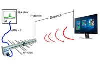
Any type of radio frequency (RF) testing requires antennas. Equipment under test may or may not have them - some devices aren't designed to broadcast but still might. But the analyzer will always require an antenna to receive whatever signal there might be, whether undertaking emissions, enclosure, or field testing.
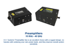
In many, if not most, testing scenarios, the antenna for reception will need a preamplifier (preamp). Technicians and engineers must boost the signal to ensure adequate dynamic range for accurate and meaningful test results.
There are a number of ways that mistakes with preamps in test configurations can lead to misleading or incorrect readings or even damaged equipment and unnecessary costs. With some attention and proper equipment matching, results will be accurate and useful, and expenses will remain at a minimum.
Signal testing essentials
EMC Product testingThere are multiple signal testing circumstances in which a preamplifier may be required. One is emissions testing. Regulatory requirements around the world limit the amount of spurious RF transmissions devices can emit to avoid generating electromagnetic interference (EMI) that can interrupt other electronics. Regulations also require monitoring ambient RF levels to ensure they do not reach prohibited levels of electromagnetic radiation.
Products like televisions, automobiles, and microwave ovens are just a few examples of those that must undergo emissions testing. Such testing typically happens in a testing enclosure, a specially designed and outfitted Faraday cage to isolate the test from outside RF interference.
Another type of testing that might need a preamplifier is testing of the enclosure itself. To ensure a valid emissions test, the enclosure must prohibit signal leakage, either from outside to in or from inside to out. Enclosures require periodic signal testing to ensure that the shielding continues to be adequate.
RF field testing, a third type that may need a preamplifier, takes place in an unshielded environment and determines the strength of signals, whether expected or not. Testing helps determine if equipment is working to specifications and if RF exposure to the environment remains within regulated levels.
All of these testing regimes share a general methodology:
- A device in one position sends a signal.
- Equipment in another position receives the signal.
- Analysis of the results provides the needed insight into device behavior.
The testing transmitter may have up to three basic parts. One is the signal source. That might be an actual telecommunications transmitter, like a cell phone, or a device that might emit some form of EMI. Depending on the source, there might be a power amplifier to increase the signal to measurable levels. There is frequently also a transmission antenna to enable broadcast of signals at measurable power levels.
The receiver also has three parts. There is always an antenna, necessary to detect the signal, as well as an analyzer for the analysis. Frequently, although not always, there is a preamp.
Importance of the preamp
Amplifiers, whether preamp or power amp, are common in testing setups because signal levels are often too low for easy or accurate measurement. The two serve different functions and face differing requirements.
A power amp might be matched to a signal source that would otherwise generate too little power to be useful. A signal generator, for example, might produce 30 dBm, or 1 watt, insufficient to generate the necessary field intensity for testing. A power amp takes the signal and, with a 50-ohm impedance cable to the transmission antenna, typically provides an output of 25 watts or more. Noise is not a large factor for a power amp, as the noise floor level is far below the broadcast signal. For testing purposes, power amps also do not need to provide linear amplification.
The preamp serves a different purpose and is frequently part of a configuration because of the testing realities. The entire range of transmission is important, particularly the lower end, to show signal attenuation and control over potential interference generation. An incoming signal, or at least part of the signal, frequently sits below or near an analyzer's noise level of -100dB to -120dB. Without amplification, the noise floor will render some or all of the signal undetectable, rendering an analysis fatally flawed.
A preamp typically provides a 40dB gain with a highly linear response, shifting the entire signal to between -60dB and -80dB, therefore above the noise floor. In essence, the preamp has the effect of lowering the noise floor because it boosts the entire antenna signal above it, which increases the dynamic range.
Although a preamp is frequently important, not all testing setups will need one. High Intensity Radiated Field Testing (HIRF), near-field testing of commercial transmitters, and some automotive and military testing commonly involve higher levels of RF fields that deliver a signal already above the noise floor. In such cases, you can connect the receiving antenna directly to the signal analyzer.
Working with preamps in testing
When using a preamp in testing, the right procedures and additional equipment, if needed, are necessary.
Tests always involve an examination of particular frequencies. Preamps need to react in a linear fashion over the incoming signal wavelengths. To maintain a linear response, the preamp must avoid both saturation and cutoff points in the semiconductor portions of the circuitry, otherwise the resulting amplified signal would put a limit on either the high end or low end.
Because linear amplifier designs by their nature support specific frequency intervals, you must match the preamp to the signal coming in, just as the antenna will need to match the received signal for optimum performance. In addition, the preamp input should match the impedance of the antenna to minimize loss.
Locate the preamp as close to the antenna as possible. Otherwise, additional cable length increases loss. Because the received power is so low to start with - which is why you use a preamp - the additional attenuation could leave an insufficient amount of signal to amplify.
Remember that the preamp will also add additional noise, typically on the level of 5dB. Plan on an additional 6dB of gain to overcome the added noise.
The preamp needs proper grounding. That means it should be grounded with the antenna to avoid potential differences and the introduction of unwanted interference, as the antenna and preamp are susceptible to electrostatic discharge (ESD).
Some types of antennas, such as broadband horns, log-periodics, and biconicals, are more susceptible to ESD. The primary reason is that these antennas incorporate an RF-matching technique that exhibits a DC short from center pin to ground. Other types, like narrowband horns, do not use the technique and are less susceptible.
Personnel touch the antenna when making adjustments or to switch it from vertical to horizontal positioning to check results under different types of signal polarization. When using more susceptible antennas, testing personnel should wear grounding straps connected to the antenna and preamp grounds. Wearing a grounding strap when using a preamp is an easy step and eliminates the need to remember which antennas might be "safe" to touch.
In the setup, avoid exposing the preamp to strong EMI or RF signals that could induce additional noise. Use enclosures when practical.
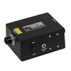
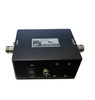
The testing setup may need additional equipment as well. At times a preamp requires an input limiter to reduce the top power level. Too high a level at input can burn out the first stage of a preamp. For example, A.H. Systems carries a preamp model (PAM-0118P) with a built-in limiter to protect the device.
The setup may also require a low pass or bandpass filter. Our company worked with a client that was testing a Bluetooth device, at a frequency range below the Bluetooth signal, with a preamp. But the Bluetooth test device emitted a signal strong enough to destroy the preamp's front end. A bandpass filter eliminated the problem.
Plan first to save total costs
For the greatest effectiveness, efficiency, and cost control in testing, planning is necessary. If possible, work with experts who understand the demands and limitations of preamps and the procedures and additional equipment needed.
Taking time up front to establish a valid, robust, and effective testing plan will ensure that the process will occur as quickly as possible, results will be accurate, and total costs will be kept to a minimum.
Welcome to A.H. Systems, inc.
A.H. Systems has been established since 1974 and manufactures a complete line of affordable, reliable, EMI test equipment. Our individually calibrated EMI Test Antennas, Preamplifiers, Current Probes and Low-Loss Cables satisfy many test standards including CISPR, MIL-STD, FCC, EN, VDE, IEC and SAE. With a wide variety of mounting configurations, we can also offer tripods and accessories that compliment other EMI testing equipment used to complete your testing requirements. We are also committed to providing all of our clients with no cost prompt and professional technical support. Manufacturing high quality products at competitive prices with immediate shipment plus prompt technical support are our goals to improve the quality of your testing requirements.
Here is a pdf version of our product catalog.