Fieldbus Products Information
Fieldbus is a suite of industrial protocols which define a digital industrial network that will replace the analog 4 – 20mA signal standards. However, Fieldbus is much more than a replacement for the 4 – 20mA standards. Fieldbus is a digital, bi-directional, multi-drop and serial communication network. The network is used to link field devices such as sensors, meters, actuators, controllers, etc. It has many advantages over other industrial networks, but perhaps the most attractive from the point of view of the user is its cost. Fieldbus allows for less electrical inventory (including wires, cables, and control room real estate). It also reduces the number of wiring diagrams and drawings, as well as the installation costs.
Field Devices
Field devices are the nodes connected to a Fieldbus network. They receive and transmit digital signals and contain low cost computing power that allows them to perform simple operations (e.g. control, maintenance, and diagnostics) on their own. Field devices are able to communicate with each other; making Fieldbus in essence a distributed control network.
In general, fieldbus devices are directly connected to programmable logic controllers (PLCs) or programmable automation controllers (PACc). In traditional analog and discrete systems, a separate cable needs to be run between each device and the PLC. Fieldbus connects all sensors in the same area to the same cable or node, reducing network complexity.
Specific fieldbus instruments also provide diagnostics and calibration for various operations such as conductivity measurement, temperature readings, and flow controls. A fieldbus can also provide drift compensation to eliminate the need for frequent recalibration.
This video gives a quick overview of the purpose and advantages of fieldbus technology.
How Does a Fieldbus Work?
Fieldbus operates as a separate communication tool to unify all process signals into one feed for a controller. Fieldbus devices allow many (hundreds) of digital and analog signals to be connected at the same time. In addition, these instruments sometimes have PID (proportional–integral–derivative) control capabilities because they contain a microprocessor. This is convenient for relieving the master controller and providing processing functions near the devices themselves.
Topology
Network topology is the way in which different devices in a system are linked together for communication. In understanding the hierarchy of devices in an automated industrial network, consider the tree topology shown below, in which communication goes from the individual instrument components to the main controller.
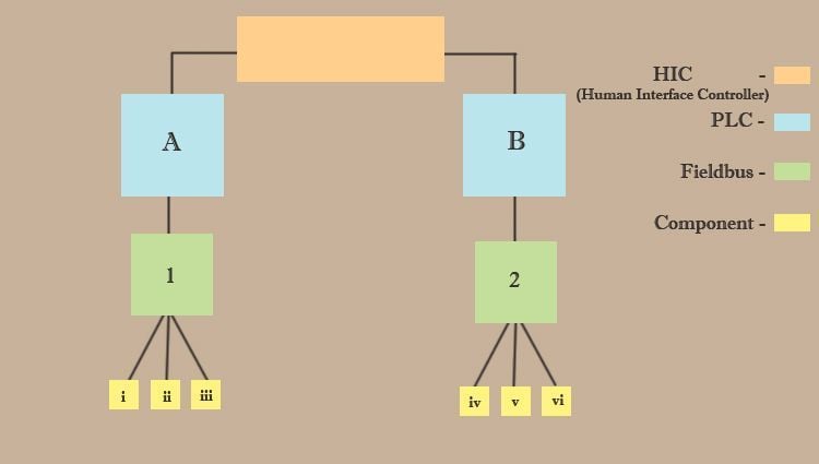
Figure 1 – Basic tree topology of a fieldbus incorporated network. In practice, hierarchies and connection diagrams can be much more complex.
Fieldbus systems can support a variety of different network topologies. These include star, daisy-chain, ring, and branch networks.
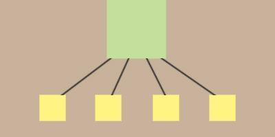
Figure 2 – Basic star network: all components connect directly to one fieldbus.
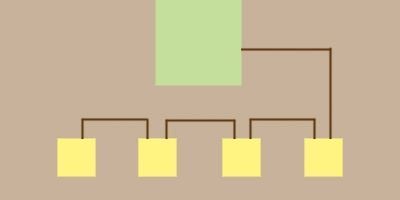
Figure 3 – Basic daisy-chain network: components connect and communicate through their neighbors in a line to the fieldbus.
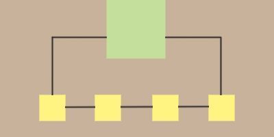
Figure 4 – Basic ring network: components connect in a circle and transmit data in one direction to the fieldbus.
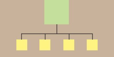
Figure 5 – Basic branch network: components each connect to one line which then transmits to the fieldbus.
Selection
Industrial buyers, when selecting fieldbus products, should first consider what protocol is compatible and suitable for their system or network. Beyond this, it is important to consider the physical specifications, performance specifications, and features of the device that best meet the needs of the operation.
Protocol Types
Protocols are the message formats and rules by which a network is designed to communicate. All devices in an operating network must be compatible with specific protocol. There are a large number of fieldbus protocols, and the most commonly encountered of these are compared in the chart below. Fieldbus Foundation was created to establish a standard for the creation of these numerous protocols to increase compatibility and communication between systems and corporations.
| Fieldbus Name | Technology Developer | Year Introduced | Physical Media | Max Devices Nodes | Max Distance (Typical) | Primary Applications |
| Profibus DP/PA | Siemens | DP: 1994PA: 1995 | Twisted pair or fiber | 32 without repeaters | 200 m | Inter-PLC communication |
| 127 with repeaters | 800 m | Factory automation | ||||
| Interbus-S | Phoenix Contact | 1984 | Twisted pair, fiber, slip ring | 256 | 400 m | Assembly, welding and materials handling machines |
| Interbus Club | ||||||
| DeviceNet | Allen-Bradley | 1994 | Twisted pair for signal and power | 64 | 500 m | Assembly, welding and materials handling machines |
| Arcnet | Datapoint | 1977 | Coax, twisted pair, fiber | 255 | 400-2000 ft | |
| AS-I | AS-I Consortium | 1993 | Two wire cable | 31 slaves | 100-300 m | Assembly, packaging and materials handling machines |
| Foundation Fieldbus H1 | Fieldbus Foundation | 1995 | Twisted pair, fiber | 240/segment | 1900 m | |
| 65,000 segments | ||||||
| Foundation Fieldbus HSE | Fieldbus Foundation | Current | Twisted pair, fiber | IP addressing | 100-2000m | |
| Essentially unlimited | ||||||
| IEC/ISA SP50 Fieldbus | ISA & Fieldbus Foundation | 1992-1996 | Twisted pair, fiber, and radio | IS: 3-7; non-IS 128 | 500-1700 m | |
| Seriplex | APC | 1990 | 4-wire shielded cable | 500+ devices | >500 ft | |
| WorldFIP | WorldFIP | 1988 | Twisted pair, fiber | 64 without repeaters | 2 km | Real-time control, process/machine |
| 256 with repeaters | >10 km | |||||
| LONWorks | Echelon | 1991 | Twisted pair, fiber, power line | 32,000 per domain | 2000 m | |
| SDS | Honeywell | 1994 | Twisted pair for signal and power | 64 nodes, 126 addresses | 500 m | Assembly, materials handling, packaging, sortation |
| ControlNet | Allen-Bradley | 1996 | Coax, fiber | 99 | 250-1000 m | Mission-critical, plant-wide networking of PCs, PLCs |
| CANOpen | CAN in Automation | 1995 | Twisted pair, optional signal and power | 30 | 25-1000 m | Sensors, actuators, automotive |
| Industrial Ethernet | DEC, Intel, Xerox | 1976 | Thin Coax, twisted pair, fiber, thick coax | 1024, more via routers | 185 m (thin) | |
| Modbus Plus | Modicon | Twisted pair | 32 per segment, 64 max | 500 m per segment | ||
| Modbus RTU/ASCII | Modicon | Twisted pair | 250 per segment | 350 m | ||
| Remote I/O | Allen-Bradley | 1980 | Twinaxial | 32 per segment | 6 km | |
| Data Highway Plus (DH+) | Allen-Bradley | Twinaxial | 64 per segment | 3 km | ||
| Filbus | Gespac | Twisted pair | 32 without repeaters | 1.2 km | Remote I/O, data acquisition | |
| 250 with repeaters | 13.2 km | |||||
| Bitbus | Intel | Twisted pair | 32 without repeaters | 1.2 km | Intelligent I/O modules, Process control | |
| 250 with repeaters | 13.2 km |
Table 1 – Fieldbus comparison chart including common fieldbus protocols, their developers and supports, accompanying specifications, and primary applications.
Table Credit: Weighing Systems
Some of the most used protocols of those compared are Profibus, DeviceNet, Foundation Fieldbus, Interbus, CAN, and LONWorks.
Profibus is a fieldbus network designed for deterministic communication between computers and PLCs. It is the most widely accepted international networking standard, being almost universal in Europe and common in North America and South America. It can handle large amounts of data at high speed and serve the needs of large installations. Based on a real-time capable asynchronous token bus principle, Profibus defines multi-master and master-slave communication relations, with cyclic or acyclic access, allowing transfer rates of up to 500kbit/s. In Profibus, multiple masters are possible, but each device output can only have one master.
Interbus was one of the very first fieldbus protocols to achieve widespread popularity. It has versatility, speed, and both diagnostic and auto-addressing capabilities. Physically, it has the appearance of being a typical line-and-drop based network, but is actually a serial ring shift register. Each slave node has two connectors, one which receives data and one which passes data onto the next slave.
Controller Area Network (CAN) is a fast serial bus that is designed to provide an efficient, reliable, and economical link between sensors and actuators. CAN uses a twisted pair cable to communicate at speeds up to 1Mbit/s with up to 40 devices. Originally developed to simplify the wiring in automobiles, it is now used in machine and factory automation products. CAN provides standardized communication objects for process data, service data, network management, synchronization, time-stamping, and emergency messages. The extensive error detection and correction features of CAN can easily withstand the harsh physical and electrical environment presented by a car.
DeviceNet is a manifestation of CAN adapted for critical factory networking purposes. At the next level are the "control" networks, including ControlNet. ControlNet was conceived as the ultimate high-level fieldbus network and was designed to meet several high performance automation and process control criteria. Of primary importance is the ability for devices to communicate with each other with 100% determinism1, while achieving faster response than traditional master/slave poll/strobe networks.
LONWorks operates over greater distances and is a practical peer-to-peer network, extensible to many thousands of points, though it can be comparatively slow and more complex.
Foundation Fieldbus is a sophisticated, object-oriented protocol that uses multiple messaging formats and allows a controller to recognize a rich set of configuration and parameter information from devices that have been plugged into the bus. Foundation Fieldbus allows a device to transmit parameters relating to the estimated reliability of a particular piece of data. Foundation Fieldbus uses a scheduler to guarantee the delivery of messages, so issues of determinism and repeatability3 are solidly addressed. Each segment of the network contains one scheduler.
Design Specifications
Design specifications of fieldbus products include modularity and the number and type of connections a device can support. These are important to consider for determining process compatibility.
- Max connections: the number of ports available or connections that can be made by components and devices.
- Connection type(s): the cables and connections compatible with the fieldbus, including coaxial and fiber optic cables.
- Modularity: the versatility of the product design. Modular fieldbus devices are designed with standard pieces, allowing for additions and expansions, such as I/O slices.
Performance Specifications
Performance specifications are used to describe how well a fieldbus product functions. Specifications that should be considered include accuracy and drift.
- Accuracy is a quantitative or qualitative property describing how close a measurement or signal is to its actual or accepted value. This is especially important for fieldbus products that also take and record measurements.
- Drift defines the changing uncertainty in the measuring or processing of a signal over time. Devices with higher drift will lose calibration over time. This property is usually given as some amount of deviation over a set time (e.g. 1 year uncertainty of ±0.10°C).
Features and Capabilities
Fieldbus products can include a number of different features and capabilities in addition to its defining communication functions. These include measurement, calibration, data analysis, documentation, and PID control.
- Measuring functions can be incorporated in fieldbus products to take the place of some simple sensors or probes that provide intermittent or continuous information regarding process conditions.
- Calibration fieldbus devices are utilized to auto-correct for component drift or temperature related calibration errors.
- Documenting functions are incorporated into fieldbus products for automatic handling and storage of information received from all connected components.
- Data analysis capability can be added to fieldbus products for aggregate data analysis from all connected components.
- PID control is a function of fieldbus products that act as controllers rather than passive couplers, providing local data processing rather than via a central PLC.
References
Weighing Systems - Which Fieldbus to go for?
Modeling and Control - Tutorial Series: Foundation Fieldbus
Fieldbus Terminology
- Determinism – The guarantee or certainty that an event (signal) will occur (transmit or receive) within a specified period of time.
- Real time – The performance required for traditional fieldbus applications in plant floor control. Performance refers to application throughout or the reaction time for an input signal to be processed by a controller, triggering an output event.
- Repeatability – The capacity of a device to measure, transmit, or receive data consistently and predictably.


