Switching Power Supply Design, 2nd Edition

Mathematically sufficient without being unnecessarily academic, this practical book's tutorial, how-to approach shows how even a novice can immediately design a complete switching power supply circuit.
All topologies discussed thus far, with the exception of the boost regulator (Sec. 1.4) and the polarity inverter (Sec. 1.5) deliver power to their loads during the time when the power transistor is turned on.
Flyback topologies described in this chapter operate in a fundamentally different way. During their power transistor on time, they store energy in their power transformer while load current is supplied from an output filter capacitor. When the power transistor turns off, the energy stored in the power transformer is transferred to the output as load current and to the filter capacitor to replenish the charge it lost when it alone was delivering load current.
The topology has advantages and drawbacks, discussed in detail below. The major advantage is that the output filter inductors required for all forward topologies is not required for flybacks. Especially for multioutput power supplies, this is a significant saving in cost and space.
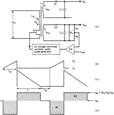
Flyback converter topology is shown in Fig. 4.1. It is very widely used for output powers from about 150 down to under 5 W. Its great initial attraction-although it is not strictly so, as will soon be seen-is that it has no secondary output inductors as have all topologies discussed thus far. The consequent savings in cost and volume of the output inductors is a significant advantage.