Rotary Encoders: What They Are and How They Work
Featured Product from Advanced Assembly, LLC.
Rotary Encoders: What They Are and How They Work
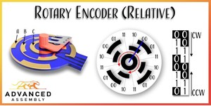
Rotary encoders are electromechanical devices that detect an axle’s absolute or relative rotational position. The resolution of the encoder determines the minimum detectable angular displacement.
Encoder discs use magnets, metals, holes, or conductors to create precise patterns in concentric rings that are then detected using magnetic, capacitive, optical, or conductive sensors.
The encoders used in many consumer electronics designs employ a conductive wiper that makes contact with copper patterns arranged in three concentric rings. One wiper finger is in constant contact with a central metallic ring, and the other two wipers contact the two interrupted outer annular arcs. Logic states are created by connecting concentric rings A and B to 3.3 V through pull-up resistors (PUR) and ring C to 0 V potential.
Binary-Reflected Gray Code
Manufacturing is full of inherently variable processes. It is impossible to make two identical parts. If the metallic patterns on the PCB vary a little bit from one part to another or the wipers aren’t exactly aligned, then it is possible for there to be a slight offset between the transitions of the different bits. The greater the number of transitions, the greater the chance of slight misalignments creating spurious logical states. For example, the transition from 0B0111 to 0B1000 (binary 7 to binary 8) involves four transitions, one for each bit. But at the transition, it is unlikely that all four transitions will be perfectly aligned. For a very specific location, the bit readings at that transition might be 0B0000, 0B0001, 0B0010, 0B0011, 0B0100, 0B0101, 0B0110, 0B0111, 0B1000, 0B1001, 0B1010, 0B1011, 0B1100, 0B1101, 0B1110, 0B1111. It is difficult for error-correction algorithms to know which bit or bits are incorrect with that many possibilities. So rotary encoders rarely ever use traditional binary counting encoding schemes.
The most common solution to this problem is using a code with a single bit change per transition. Then, no matter what manufacturing anomalies occur in the transition regions, there is a single distinct location where the transition occurs. The encoding scheme is referred to as gray-code after the inventor Frank Gray.
Absolute rotary encoders need to know their position at any time, even when power has been removed from the sensor for an extended period, and there is no battery backup or opportunity to return to a known angular position. Those sensors add additional concentric annular rings and, therefore, additional bits to the encoder.
You might find 2-bit relative encoders in audio equipment, acting as volume, tone, balance, or mixing knobs. Relative encoders are also found attached to motors and gears, where they can detect the position and integrate to determine angular velocity and angular acceleration. 3-bit, 4-bit, and n-bit absolute encoders are found on products with rotary selector knobs, such as washing machines and dryers. They’re also widely used for industrial applications, such as CNC servo motors, robot arms, actuators, etc. It’s also very common to find absolute encoders with integrated circuitry that convert the grey-code to traditional binary code.
Circuit Diagram
At its heart, the rotary encoder is simply a set of two switches that change state at slightly different angular positions to output a series of out-of-phase square waves. To convert the switch position to logic levels, designers use pull-up resistors (PUR) that permanently tie the switch outputs (A&B) to the positive power net (Vcc) and the shared switch input connections directly to the ground potential (0 V).
The switch outputs will approach Vcc whenever the switch is open, which represents a logic high state. The switch outputs will quickly reach ground potential when the switches are closed, representing a logic low state. A low-pass filter made of a resistor and capacitor ensures that any switch bounce is not passed on to a microcontroller and detected as an erroneous state.
Pull Up resistor
The wetting current (minimum current) rating and the source voltage define the upper limit for the PUR. For example, if the datasheet specifies a 0.5 mA wetting current and you will use a 3.3 V DC source voltage, Ohm’s law provides a maximum resistance of 6.6 kΩ. If the current falls below the designated level, it might not be possible for the current to pass through the oxide layer that forms on the surface of the contacts and the wiper.
The maximum current rating in combination with the source voltage defines the lower limit for the PUR. For example, a 3.3 V DC source voltage with a 2 mA maximum current would require a minimum resistance of 1650 Ω.
1650 Ω resistors are available, as are 6.49 kΩ 1% resistors — but they are expensive and unnecessary in this application, and therefore a poor choice.
For this example, the following 5% resistor values from the E-24 series are acceptable options: 1.8 kΩ, 2.0 kΩ, 2.2 kΩ, 2.4 kΩ, 2.7 kΩ, 3.0 kΩ, 3.3 kΩ, 3.6 kΩ, 3.9 kΩ, 4.3 kΩ, 4.7 kΩ, 5.1 kΩ, 5.6 kΩ, 6.2 kΩ. But which one do you choose? That depends on a few different things. If your device is battery-operated, you should choose the highest resistance value possible to limit the power dissipated through the resistor. But for most applications, you should choose a resistance value that you can use elsewhere in your circuit. Anytime you can decrease the number of line items in your BOM, you will reduce the overall cost to manufacture your project.
Follow us on:
Advanced Assembly Capabilities
Advanced Assembly
Advanced Assembly is located in Colorado and is the #1 printed circuit board assembly company that provides services specifically for engineers needing fast prototype PCB assembly. The company’s assembly services are in demand by design engineers across all industries and multiple countries. Customers include 23 of the Fortune 500 companies such as 3M, Agilent Technologies, GE, HP, Microsoft, Lockheed Martin, Honeywell, Raytheon, and L-3 Communications. Examples of customer projects assembled by Advanced Assembly include automated insulin dispensers, sports scoreboards, army drone helicopters, hybrid automobiles and more.
To quickly assemble orders with extreme attention to accuracy, Advanced Assembly developed a proprietary software solution that automatically programs an assembly machine using customer-provided data. Now it is cost-effective to use machines to assemble any size order, even one board, and quality is improved by eliminating the potential for human error.
Engineers lean on Advanced Assembly's in-house expertise for advice and new services have been added to make outsourcing assembly even easier. One of the most unique value-added services offer is the ability to view designs prior to assembly. Advanced Assembly creates a digital image of a customer’s design based on actual manufacturing data. This helps customers fix potential problems before they cause delays or costly rework. No other competitor provides this service, which Advanced Assembly offers free of charge.
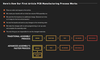
Here’s How Our First Article PCB Manufacturing Process Works
- Place an order and request a first article.
- We create your boards with an initial low-volume PCB assembly run.
- We send the first boards at no additional charge. (General turn time is 3-5 days for the first article boards.)
- You test the boards and send us any changes to the remaining order.
- We make the changes with no extra programming or set-up costs and complete the assembly order.
- The only thing you are responsible for are the changed materials