ANSI Roller Chain Sprockets Information
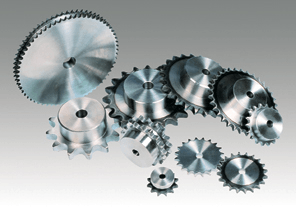
Roller chain sprockets engage chain drives in power transmission and conveyor systems, though sprockets can engage any perforated material. Chain drives can be highly efficient and reliable in applications with limited shock and torque loads, provided the drive is well maintained. Chain drives can produce a mechanical advantage as speed reducers/increasers, created by utilizing sprockets of varying sizes. While related to gears, a sprocket's main differences are that it never engages another sprocket directly and a sprocket's radial projections require a sloped profile for smooth chain engagement and release.
Sprockets conforming to ANSI standard B 29.1 are not meant to engage roller chains of any other parameter. ANSI conforming roller chain is smaller and somewhat weaker than its European counterpart and further discrepancies are detailed below.
Video Credit: woodmn09 via Youtube
Sprocket Operation
Sprocket and chain interaction. Image Credit: The Complete Chain Guide
The sprocket's teeth mesh within a roller chain, thereby transferring rotational energy between parallel axes over distances. Sprockets have several points of high-friction contact with a roller chain, which is important to efficient rotation, but also wears the sprocket and roller chain quickly. This is combated with lubricated bushings around the pin that the sprocket grasps, as well as between the plates that hold the chain together. If mounted to a shaft for the purpose of supplying or receiving motion, the sprocket is called a dry sprocket. If the sprocket is positioned in the chain drive for stabilization, chain rerouting, or additional friction, it is known as an idler sprocket. Some roller chain transmissions feature a derailleur, such as on a bicycle, so the mechanical advantage can be adjusted without replacing a sprocket or stopping the transmission.
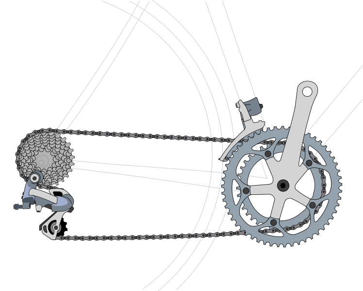
Dual derailleurs. Image Credit: Wikimedia
Sprocket Production
Like gears, sprockets usually are milled or forged, but custom sprockets may be flame-cut. Unlike gears, sprockets may be produced in halves or segments to aid in transportation and integration into the drive. A sprocket can also be produced in a manner so its teeth are removable and with an integral shaft, making replacement less costly and time consuming.
A diverse selection of materials is available for sprocket production. Metal is most common, but non-metallic versions and hybrid versions, like metal wheels with plastic teeth, exist as well. Sprocket manufacturers tend to produce sprockets to interact with either International Organization for Standardization (ISO) or (American National Standards Institute) ANSI roller chain, depending upon the manufacturer's primary marketplace.
Video Credit: Cogmatic Machines / CC BY-SA 4.0
International Standards
The ANSI roller chain standard is slowly out-phasing ISO standards, with an estimated 15% European market share due to a large import of American and Asian machinery. Other international standards exist in waning popularity.
ANSI
North American and some Asian sprocket manufacturers have adopted ANSI code B 29.1, which edicts design, dimensions, and interchangeability within a chain drive. ANSI sprockets typically do not last as long as their European counterparts due to smaller tooth pitches but have a clear mathematical theme and simple design. ANSI covers eight different strand types of sprockets: single-strand, double-strand, triple-strand, and multiple-strand (4, 5, 6, 8, 10).


Single-strand sprocket; Multiple-strand. (4) sprocket Image Credits: Saab Engineering Ind. | Emco Engineering
ANSI sprockets are notably characterized by 'type', which indicates the sprocket's hub style. Hub styles offer unique mounting shaft mounting configurations, which are further covered under mounting options. There are four styles.
Style A - a flat sprocket with no hub
Style B - a sprocket with a hub on one side
Style C - a sprocket with hubs on both sides
Style D - a sprocket with a bolted hub attached to a plate

Image Credit: Martin Sprocket
Sprockets adhering to ANSI standards are also given preferred numbers, with each sprocket earning a number designation in relation to the tooth pitch and tooth-gap diameter. The left-hand digit is representative of the pitch, incremented in eighths of an inch. The right-hand digit of the number designates the type of chain to use with the sprocket, with 0 for standard chain, 1 for lightweight chain, and 5 for rollerless, bushed chain.

Image Credit: Wikimedia
An ANSI sprocket number may have suffixes of letters and numbers, which will indicate the number of strands and any additional attributes of the sprocket. For example, a sprocket named 25-2H would be a size 25 sprocket, with double-strands (2) and the ability to handle chains with thicker plates (H). A 35-SS would be a size 35, single-strand sprocket, with stainless steel construction. Common suffix abbreviations include DC for dual capacity, V for hardened pins, H for heat-treated plates, NP for nickel plated, HP for hollow pins, SB for side bend, NM for non-metallic, BR for brass, CD for cadmium plated, Zi for zinc plated, and CH for chrome plated.
ISO
ISO standard R606 dictates sprocket uniformity for most European and African nations. This standard is in relation to British Standard Chain, which is dimensionally different than chains meant for ANSI sprockets. ISO sprockets have large pitches that are measured in sixteenths of an inch, but are expressed in metric units. British Standard Chain was developed before American-styled chain, but was limited in its development by what materials were readily available as roller chains evolved. The outer plates of an ISO chain are taken from the chain size one level above the application requirements. This led to bulkier, heavier chain with a longer fatigue life that is still used today. ISO standard R606 only includes single, double, and triple-strand sprockets.
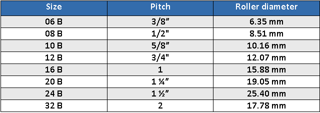
In ISO naming conventions, the 'B' indicates adherence to European standards. An ISO sprocket may also feature a number as a suffix, which will indicate the number of chain strands. A 16B-2 sprocket will feature a pitch of one inch along with a double-strand spool.
Other
Japanese roller chain transmissions are subject to JIS standards B 1801, B 1802, and B 1803, but these parameters are mostly limited to mainland Japan. Korean industrial sprockets fall under Korean standard KS B 1407. Finally, Germany's industries produce chain in dimensions very similar to both British and American standards, but under Deutsche Institute fuer Normung (DIN) codes 8187 and 8188, respectively. These industrial standards are becoming increasingly rare, but are worth mentioning for their previous use. Consult a sprocket manufacturer or retailer for details and the interchangeability of these standards.
Roller Chain Sprocket Configurations
Within international standards sprockets are conceptually basic mechanical devices. However, their versatility leads to many contrasting styles.
Sprocket Strands
Typical roller chain drives will employ a single roller chain with its respective sprockets. It is not uncommon though for multiple-strand sprockets to be incorporated onto a single hub so a load is transmitted through numerous chains, with up to as many as ten chains. Multi-strand sprockets are used in conveyor applications to maintain a uniform speed. By distributing a load across multiple sprockets, each chain and sprocket has an enhanced performance life. Multiple-strands are helpful in drives where the horsepower required exceeds a chain's horsepower rating. This is also common in applications where the transmission may need to continue despite a roller chain transmission failure.


Double-strand sprockets in use. Image Credits: Martin Sprocket | Specialty Equipment
Sprocket Body Style
Common sprocket body features include the following:

Image Credit: Rexnord
-
Arms: This type of sprocket is used where large sprocket sizes are needed. The use of arms lowers weight-- and therefore inertia--and cost.
-
Split body: By segmenting the sprocket body the sprocket is easier to assemble and disassemble from around a shaft.
-
Plate body: A plated body provides stronger sprocket structure, and is typical on smaller circumference sprockets.
-
Fabricated cuts: Fabricated, cut sprockets are flame cut and have flame or induction hardened components.
-
Flanged: With a short extension on the sprocket rim, the chain's plates rest on the sprocket as well, allocating some load from the chain's pins. These are sometimes called "chain-saver sprockets" because of the enhanced chain lifespan.
 Sprocket Tooth Style
Preferably, sprockets should have no less than 17 teeth, especially at high speeds or loads. More teeth enhance the wear life of the sprocket proportionally, as well as the chain. Tooth height is based on wear resistance, along with smooth chain engagement/release. Teeth are usually of the same material as the sprocket, though teeth with plastic inserts exist as a cost-efficient option. Other removable teeth options allow the sprocket's pitch to change.
Hardening sprocket teeth greatly enhances sprocket life and is recommended for reductions of 4:1 or greater, for slow speed drives, or when safety or abrasive conditions are less than standard. Induction and flame hardening are the most common methods.
A style of sprocket with no teeth exists in the form of a traction wheel. Technically similar to a pulley, the traction wheel's main advantage is that it won't destroy equipment if overloaded or obstructed. The traction wheel provides a sufficient level of friction to drive the transmission, and is most common in lifts and conveyor belts. The traction wheel can also be used as an idler sprocket, such as in a bulldozer's caterpillar propulsion.


Image Credits: Rexnord | Colour Box
Other tooth styles are meant to reduce fatigue on the chain drive transmission.
|
Image Credit: Heavy Equipment Forums
|
|
|
|
Image Credit: Motion System Design |
|
Image Credit: Old Bicycle Junk |
|
Image Credit: Tsubaki |


Roller Chain Sprocket Specifications
Roller Chain Sprocket Performance
After determining the style and standard of a sprocket, performance attributes become the most prominent conditions of sprocket selection.
Transmission Shock Control: The amount of shock a roller chain drive is subjected to alters the requirements of the sprocket. The shock can be classified into three parameters.

Table I Credit: Martin Sprocket
Transmission Input: The source of the transmission, as well as environmental factors, also changes sprocket selection.

Table II Credit: Martin Sprocket
Transmission Horsepower: Horsepower supplied to the sprocket should be supplemented to compensate for transmission disturbances and the input power. This is known as service horsepower and is determined with the table below.

Table III Credit: Martin Sprocket
Transmission Pitch: Selecting the smallest pitch chain for the specified drive's RPM requirements will increase the options for the chain's corresponding sprockets. If the horsepower supplied at the required RPM is greater than the horsepower rating of the largest pitch available, a multiple-strand drive should be considered for the application.
Driving Sprocket: Although 17 teeth are the recommended minimum for a drive sprocket, as little as 7 teeth are commonly available. When the maximum bore of a 17 tooth sprocket will not accommodate a required shaft, a sprocket with more teeth should be implemented. Hardened teeth are recommended for sprockets with 25 teeth or less.
Driven Sprocket: The sprocket receiving motion is determined by the size of the drive sprocket and the desired speed increase/reduction. The recommended maximum ratio is 7 to 1. For higher increases or reductions, multiple strands should be used.
In ratio transmissions where the chain may wrap less than 120° around a sprocket, idler sprockets are recommended to increase the grip between the sprocket and chain, such as in the instance below.

Image Credit: Wolter Pyro Tools
Center Distance: The distance between the transmission sprocket centers must always be greater than one-half the sum of the sprocket outside diameters to avoid interference with the teeth. In transmission ratios greater than 3 to 1, the center distance must be greater than the sum of the sprockets. Some applications may be able to accommodate adjustable center differences which can help keep roller chains taut.
Longer center distances give better chain wrap around a sprocket. For common applications, a center distance of 30 to 50 chain pitches is recommended for best results. For transmissions with variable loads, 20 to 30 pitches may be suitable. On transmissions longer than 80 chain pitches in length, idler sprockets should be used to support the chain.
Alignment: Having sprockets that are on the same vertical plane provides a uniform load distribution across the sprocket and provides optimum sprocket and chain life. Misalignment can be prevented with the use of thrust bearings, quality shafting, and stable foundations. Periodic maintenance should include alignment inspection.

Common sprocket misalignments. Image Credit: Renold
Lubrication: Lubrication for sprockets, in the form of oil, provides effective cooling and impact dampening at high speeds. Quality, non-detergent oil is best suited for sprockets and roller chains. Heavy, greasy oils will not sufficiently penetrate the small clearances in roller pins, plates, and rollers.
Lubrication to sprockets and roller chains can be applied in four ways. Manual lubrication is applied periodically with a brush or oil spout. Oil baths provide constant lubrication to a roller chain in an oil-tight casing. Oil steam lubrication supplies the lubricant to the inner part of a chain in a circulating pump. Oil drips are similar to oil streams, but supply a lesser amount of oil to the chain.
Lie of Chain Transmission: Chain drives can positioned horizontally, vertically, inclined, or in virtually any other configuration. The loaded chain strand can be uppermost or lowermost, but for vertical drives the driven sprocket should remain on the bottom, if possible, to reduce maintenance.
Sprocket Replacement: Rapid wear and deterioration is the leading drawback in chain drives. While lubrication and inspection can extend the life of a sprocket, it will inevitably fail with consistent use, though should last through several roller chains. Sprocket wear is noticeable as a ground, inward cut into the tooth. The sprocket may begin to resemble a circular saw blade.
A mathematical formula exists to help determine when to replace a sprocket. If the depth of the erosion along the tooth (x) has reached a value equal to 10 percent of the tooth width (Y) across the pitch diameter (PCD), the sprocket should be replaced.

Image Credit: Renold Jeffrey
Sprocket Dimensions
Bottom diameter/caliper diameter (B.D./C.D): This is the distance across the sprocket from the bottom of opposite tooth spaces. If the sprocket has an odd number of teeth there will be no exact opposite space, so caliper diameters are the measurement across from tooth spaces nearly opposite.


Sprocket Mounting
A variety of mounting options are available for sprockets of any design. Hubs can offer specialty mounting options. Following are some common mounts.
|
Image Credit: Grab Cad |
|
Image Credit: Chevelles |
|
Image Credit: CNC Parts |


The following chart shows specialty hub mounts.
|
Image Credit: Armortek |
|
Image Credit: Emerson Power Trans. |


Roller Chain Sprocket Applications
Roller chain sprockets are found extensively in many industries. Although it didn't become a prominent technology until the late 19th Century, Leonardo da Vinci produced sketches of roller chains about 300 years earlier. Bicycles and motorcycles use roller chains to connect their road wheels to the vehicle's energy source. Sprockets are used in film projectors and film cameras, but use perforated film stock instead of roller chains. Forklifts provide vertical lift with sprockets and roller chains. Wind mills and water mills connect machinery to the power source with chain drives. Perhaps the mechanically largest version of a roller chain transmission would be the tread drive of a main battle tank.
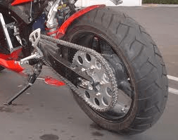
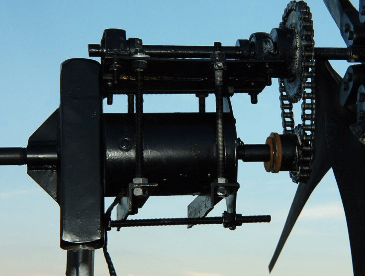
Image Credits: Why Bike | Watch TV
Resources
Martin Sprocket & Gear, Inc. - Sprockets
The Complete Guide to Chain - 1.3 Sprockets
Tsubaki Canada - Made-to-Order Sprockets .pdf
Wikipedia - Sprocket; Roller chain
Gizmology - Notes on Sprockets and Chains
Image Credits:
All Products | Drill Spot
- Alabama
- Arkansas
- California
- Connecticut
- Florida
- Georgia
- Iowa
- Illinois
- Indiana
- Kansas
- Kentucky
- Louisiana
- Massachusetts
- Michigan
- Minnesota
- Missouri
- North Carolina
- Nebraska
- New Hampshire
- New Jersey
- Nevada
- New York
- Ohio
- Oregon
- Pennsylvania
- South Carolina
- Tennessee
- Texas
- Washington
- Wisconsin
- West Virginia
- >5"
- 100 (1 1/4")
- 120 (1 1/2")
- 140 (1 3/4")
- 160 (2")
- 180 (2 1/4")
- 200 (2 1/2")
- 240 (3")
- 25 (1/4")
- 320 (4")
- 35 (3/8")
- 40 (1/2")
- 41 (1/2")
- 50 (5/8")
- 60 (3/4")
- 80 (1")
- All Plastic
- Ball Bearing
- Double
- Idler Sprocket
- Set Screw(s)
- Simple Bore
- Single
- Steel - Hardened
- Steel - Stainless
- Steel - Standard
- Tapered Bushing
- Triple
- Type A (Hubless)
- Type B (Hub One Side)
- Type C (Hub Both Sides)