Advanced Drilling Solutions: Lessons from the FSU, Volume I

Examining historical trends in drilling technologies, this volume provides coverage of downhole motors and oil well drilling optimization (KTW-Key Technological Wells drilling method).
As mentioned earlier, PDMs hold promise for various drilling applications. This subsection presents a description of various PDM designs, as well as the theory and principles of their operation, characteristics, and spheres of application.
From 1966 through 1975, designers and engineers carried out development work and built the commercially produced D-series PDM. Initially, engineers built and tested the motors with diameters of 85 mm and 127 mm. Experience indicates that PDMs perfectly match current drilling practices. They do not require use of special drilling tools, pumps, or other equipment. [37]
All PDMs had a uniform principal design. The D-type DHM (Fig. 2-52) consisted of two sections: a motor and a spindle.
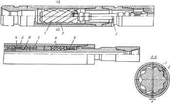
The motor section included a stator (1), a rotor (2) that was essentially an eccentric screw mechanism, and a double-hinged joint (3). The stator was made as steel housing with a rubber faced inside surface that had 10 specially shaped spiral teeth. The stator was connected to a string of pipes through a sub. The steel rotor had one tooth less than the stator, and its axis was offset from the stator axis by an eccentric value. The two-step working elements (stator and rotor) were used in the motor.
The screw surfaces profile could be based on the centroid and off-centroid hypo- and epicycloidal engagements. The rotor and stator screw surfaces were left-handed to enable clockwise rotation of the rotor (relative to its axis). Through a double-hinged...