- Point 1: Generating Drawing Views Using the Drawing Module of Autodesk Inventor
Deepak Maini
Parts created in the Part module or assemblies created in the Assembly module can be represented as 2-D entities on a sheet by generating their drawing views. There are various drawing views that you can generate in Autodesk Inventor, such as base, projected, section, auxiliary, detail, and broken. It is also possible to sketch a drawing view in Autodesk Inventor.
You can also edit the drawing views by rotating, copying, moving, or deleting them. You can also modify the drawing views and add dimensions and text to them.
This ReferencePoint explains the various types of drawing views in Autodesk Inventor and how to generate them. It discusses how to edit and modify the drawing views and add dimensions and text to them.
Setting Drafting and Sheet Options
The drawing views are generated in the Drawing module of Autodesk Inventor. To invoke the Drawing module of Autodesk Inventor, double-click Standard.idw in the Default tab of the Open dialog box, as shown in Figure 1-1-1:
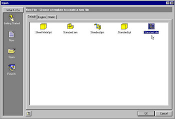 Figure 1-1-1: Invoking Drawing Module
 | Tip | You can also invoke the Drawing module using the other .idw files available in the English and Metric tabs of the Open dialog box. Note that the Drawing module invoked by selecting the .idw files in the English and Metric tabs is assigned a predefined drafting standard. For example, if you open the ISO.idw file in the Metric tab, the new drawing file is assigned the ISO... |
Copyright SkillSoft Corporation 2002 under license agreement with Books24x7


 TABLE OF CONTENTS