In the following example, an extremely formalistic but instructive approach to the setting up of a design check table is shown.
E.3.1: Design check table of a jacketed autoclave
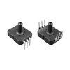
The jacketed autoclave is sketched in Fig. E.3-1, and the process cycle is shown in Fig. E.3-2.
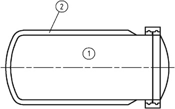 Figure E.3-1: Jacketed autoclave.
 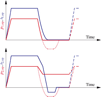 Figure E.3-2: Process cycle.
 The pressure and temperature increases in Chamber 1, denoted by p 1,op and t 1,op, are planned and controlled to occur concurrently with those in Chamber 2, denoted by p 2,op and t 2,op, respectively. The concurrent pressurization in both rooms is not ensured, and, therefore, the operating pressures (and temperatures) have to be considered to be independent. After the process period at high temperatures, the heating medium in both chambers can be blown out, and replaced by cold water in Chamber 2. The cooling period in Chamber 1 is planned to end at ambient conditions. Negative pressures are not planned, but cannot be excluded either condensation can occur under reasonably foreseeable conditions. For Chamber 2, condensation, and thus negative pressure, is planned as a possible alternative process. Consequently, the four process parameters p 1,op, t 1,op, p 2,op, and t 2,op, are considered for the design check table to be independent.
Table E.3-1 is the decision table for these four independent actions under normal operating load cases. A plus sign in the first four rows refers to an...