Pressure Vessel Design: The Direct Route

The main purpose of the examples given here is not to discuss routine procedures in the admissibility check of supporting structures, but to discuss the usage of the partial safety factor concept in the context of these routine procedures.
In this example two load cases, each with three sub-cases, are considered:
NOLC 5.1: Operating weight + Wind
TLC 5.1: Self-weight = Fluid weight + Wind
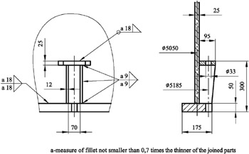
Geometry of lower end of the skirt and base ring: see Fig. E.8.1.
Figure E.8.1: Skirt geometry of reactor column.
Material of base ring: Steel EN 10028 P265GH
Material of anchor bolts: Steel EN 10025 S235JRG2
Material of foundation: Structural concrete C25/30
Self-weight: [12] F SW = 3.48MN
Operating weight: [13] F O = 3.6MN
Fluid weight during hydraulic test: F F = 2.68MN
Wind: [14]
Resultant (horizontal) force according to the (local) code for wind action: F W=53.49 kN.
Resultant moment with respect to the centre point of the base (ring): M W = 0.6096 MN m
This load case deals with uplifting weight is favourable, but wind action is unfavourable.
Design value of the operating weight:
Design value of the wind moment
Resultant longitudinal force (per unit length) in the skirt at the junction to the base ring due to operating weight:
where D m=5050 mm...