Power Electronics and Motor Drives: Advanced and Trends

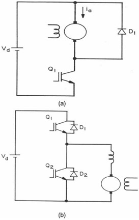
A voltage-fed converter is fed ideally by a zero Thevenin impedance voltage source. Figure 4.1(a) shows a dc-dc buck or step-down converter, where the supply dc voltage ( V d) is converted to variable dc voltage at the motor terminal to control its speed in one quadrant only. The IGBT generally operates on an on-off duty cycle basis at fixed switching frequency. When it is on, the V d is applied to the load and its current tends to build up. When Q 1 is off, the freewheeling diode D 1 circulates the load inductive current shorting the load (assuming continuous conduction). The average motor voltage is always less than V d. Figure 4.1(b) shows two-quadrant speed control by a buck-boost hybrid converter.

In the buck mode, as just discussed, the device Q 1 chops the supply voltage and D 2 freewheels. In the boost mode, Q 2 and D 1 are active. If Q 2 is on, the counter emf of the motor tends to builds up the current in the armature inductance, which then flows to the line when Q 2 is off. Thus, the machine operates in the regenerative mode when the motor's mechanical energy is converted to electrical energy and fed back to the source. In this mode, V d is...
