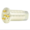
4 Channel RF Rotary Joint
Featured Product from JiuJiang Ingiant Technology Co., Ltd.
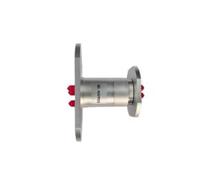
Product Overview
This four-channel RF rotary joint is a hybrid slip ring: one flange-mounted rotating assembly that carries four independent 50 Ω coaxial channels (CH1 to CH4) from DC to 2.5 GHz, together with a DC power circuit rated 2 A at up to 440 VAC/DC. Each RF channel terminates in a standard SMA-F connector, so the unit drops into an existing coax chain without adapters, phase-matched jumpers or a custom harness.
The target application is equipment that must keep radiating, keep receiving and keep powered while the antenna, turntable or pedestal turns continuously through 360 degrees: air traffic control radar, satellite earth station antennas, microwave test turntables and automated control heads where an unlimited rotation angle is a design requirement rather than a convenience.
One Rotating Interface Instead of Two
Rotating antenna systems normally solve transmission twice: one device for RF, a second device for power, plus a cable wrap, a harness twist allowance or a limited-rotation stop. Each extra joint adds insertion loss, a reflection point, a connector to torque, and a line item to qualify and to spare.
This unit merges the four RF paths and the power path into a single interface with published loss, isolation and life figures. Mechanical envelope, cable routing, acceptance test and spare-part stock all stay in one place, which is usually where RF rotary joint projects lose the most schedule time.
Key Features and Benefits
-
Four independent RF channels, DC to 2.5 GHz. Each channel has its own VSWR, insertion loss and variation limits, so a transmit/receive pair, dual-polarisation feed or a live channel plus a spare can share one rotating interface.
-
Hybrid RF and power transmission. Power contacts rated 2 A at up to 440 VAC/DC feed a rotator drive, a mast-mounted amplifier, a sensor or control electronics without adding a second slip ring.
-
High power handling. 200 W peak and 20 W average at 1 GHz per channel cover pulsed radar operation and continuous microwave test signals on the same hardware.
-
Stable RF performance over rotation. VSWR stays at or below 1.3 with variation no greater than 0.05 (CH1) and 0.1 (CH2 to CH4); insertion loss stays at or below 0.5 dB with variation no greater than 0.1 dB, so readings do not swing as the rotor turns.
-
50 dB channel isolation. High-power transmit energy stays out of the receive path and out of adjacent channels, which matters for co-located transmit and receive antennas.
-
Low, steady contact resistance. Variation is held to 10 mΩ maximum, keeping voltage drop and heat predictable in the power circuit over service life.
-
Built for outdoor and industrial cabinets. IP51 sealing, an operating range of -30 °C to +80 °C and up to 85 % relative humidity.
-
Long service life at speed. 100 rpm maximum rotation with a minimum service life of 5 million revolutions, equivalent to years of continuous azimuth scanning.
Technical Specifications
Per-channel RF parameters (each channel is specified individually, not as a group average):
|
Parameter
|
CH1
|
CH2
|
CH3
|
CH4
|
|---|---|---|---|---|
|
Interface type
|
SMA-F (50 Ω)
|
SMA-F (50 Ω)
|
SMA-F (50 Ω)
|
SMA-F (50 Ω)
|
|
Frequency range
|
DC-2.5 GHz
|
DC-2.5 GHz
|
DC-2.5 GHz
|
DC-2.5 GHz
|
|
Peak power (max)
|
200 W
|
200 W
|
200 W
|
200 W
|
|
Average power (max)
|
20 W at 1 GHz
|
20 W at 1 GHz
|
20 W at 1 GHz
|
20 W at 1 GHz
|
|
VSWR (max)
|
1.3
|
1.3
|
1.3
|
1.3
|
|
VSWR variation (max)
|
0.05
|
0.1
|
0.1
|
0.1
|
|
Insertion loss (max)
|
0.5 dB
|
0.5 dB
|
0.5 dB
|
0.5 dB
|
|
Insertion loss variation (max)
|
0.1 dB
|
0.1 dB
|
0.1 dB
|
0.1 dB
|
Shared electrical, mechanical and environmental parameters:
|
Parameter
|
Value
|
|---|---|
|
RF channels
|
4 (CH1 to CH4), SMA-F, 50 Ω
|
|
Power circuit
|
2 A rated current, 440 VAC/DC working voltage (max)
|
|
Contact resistance variation
|
10 mΩ (max)
|
|
Channel isolation
|
50 dB
|
|
Protection grade
|
IP51 (dust protected, protected against dripping water)
|
|
Operating temperature
|
-30 °C to +80 °C
|
|
Operating humidity
|
85 % RH or less
|
|
Rotation speed (max)
|
100 rpm
|
|
Service life (min)
|
5 million revolutions
|
|
Mounting
|
Flange-mounted rotor and stator; interface drawing issued per order
|
Typical Applications and What to Confirm
The table maps common uses to the parameters that decide whether this standard unit fits or needs a custom variant.
|
Application
|
What the unit does there
|
Confirm before ordering
|
|---|---|---|
|
Air traffic control and surveillance radar pedestal
|
Continuous azimuth rotation while pulse power and DC feed pass through the same axis
|
Peak power and duty cycle, azimuth speed, required life in revolutions
|
|
Satellite communication and earth station antennas
|
Transmit, receive and power on one rotating axis; 50 dB isolation separates the two paths
|
Band edges against the 2.5 GHz limit, isolation margin for co-located TX/RX, outdoor enclosure plan
|
|
Microwave test turntable and rotary test fixture
|
Four measurement paths rotating with the device under test, with low loss variation for repeatable readings
|
Insertion loss variation, cable phase stability, rotation speed and stop-and-measure cycles
|
|
Rotating antenna for telemetry, direction finding or electronic warfare
|
Multichannel feed and control power on a single rotating head
|
Channel count and connector type, isolation between adjacent channels, shock and vibration environment
|
|
Automated control systems needing 360 degree RF and power
|
RF sensing on a rotating head plus a 2 A circuit for drives and sensors
|
Continuous versus limited rotation, torque budget, cable routing space
|
How This Unit Fits Into an RF Chain
-
Budget the loss before you buy. At 0.5 dB insertion loss plus worst-case mismatch loss of about 0.07 dB (VSWR 1.3 equals roughly 17.7 dB return loss), one pass through the joint costs about 0.57 dB. Use that figure in EIRP and G/T planning rather than assuming an ideal joint.
-
Read the variation numbers, not only the maximums. A 0.5 dB insertion loss is acceptable in most links, but a loss that changes by 0.1 dB with rotation shows up as amplitude ripple in a rotating measurement or as level drift in a scanning radar. The variation limits in the table are the numbers that protect measurement repeatability.
-
Compare by attributes. Channel count, connector type, frequency range, VSWR, insertion loss, isolation, power rating and IP grade are all published here, so the unit can be matched to a requirement list without a round of e-mails.
-
Keep the parts list short. Four RF paths plus power in one body removes a second rotary device, a cable wrap and the harness design that goes with them, which also reduces spares and qualification work.
-
Plan the acceptance test up front. State the frequency points, the VSWR and insertion loss limits and whether isolation is measured with the power circuit energized, so the incoming inspection matches the specification you designed to.
Integration and Installation Notes
-
Connector care. Use 50 Ω SMA cable assemblies with correct mating torque; tighten on the connector body, not by twisting the housing. For coherent multichannel systems, specify phase-matched jumpers between the joint and the feed.
-
Flange and alignment. Mount on a flat, rigid surface with the mating flange concentric to the rotation axis. Eccentricity and runout appear as VSWR variation long before they appear as mechanical noise.
-
Sealing. IP51 covers dust protection and dripping water. For uncovered outdoor pedestals, add a shroud or a sealed enclosure rather than relying on the joint alone; the SMA interface is the usual water entry point.
-
Power and thermal margin. The 20 W average rating is quoted at 1 GHz. At higher frequency and continuous duty, confirm the derating with the factory before fixing the transmitter budget.
-
Isolation versus receiver sensitivity. 50 dB isolation is a strong but finite figure. Check it against your co-located transmit power and receiver noise floor, and add an external filter or duplexer where the margin is thin.
-
Grounding path. Bond the stator flange to the pedestal ground so that the joint body is not the only return path for fault current.
-
Condition monitoring. A slow rise in VSWR or insertion loss, rather than a sudden failure, is the usual wear signature of a rotary joint. A periodic sweep through rotation supports predictive maintenance.
Custom Configurations and OEM/ODM Support
This product is built to order, and the four-channel DC-2.5 GHz SMA-F version is one point in a wider family. Common customisation requests:
-
Frequency range. Narrower band for cost and loss optimisation, or an extended upper limit where the system requires it.
-
Connector types. N-type, TNC and 2.92 mm interfaces in place of, or mixed with, SMA-F.
-
Flange and mounting. Different flange diameters, bolt patterns and shaft interfaces to match an existing pedestal or gearbox.
-
Hybrid configuration. More or fewer RF channels, additional power or signal circuits, and combined configurations within one housing.
-
Mechanical variants. Rotation speed, service life target and environmental treatment discussed per project.
-
OEM/ODM. Private label, custom marking, project-specific documentation and packaging for series programmes.
How to Specify and Request a Quotation
Send the following points and a quotation can be prepared against a defined configuration instead of a generic offer.
|
Item to specify
|
What to send
|
|---|---|
|
Number of RF channels
|
Channel count and function per channel (TX, RX, spare, sense)
|
|
Connector type
|
SMA-F, N, TNC or 2.92 mm, and male or female on each port
|
|
Frequency range
|
Operating band and the measurement points used at incoming inspection
|
|
Power
|
Peak power, average power, pulse width and duty cycle per channel
|
|
RF limits
|
Acceptable VSWR, insertion loss and isolation, plus permitted variation over rotation
|
|
Power circuit
|
Voltage, current and number of power or signal circuits required
|
|
Mechanical interface
|
Flange drawing, shaft coupling, available envelope, rotation speed and life target
|
|
Environment
|
Indoor or outdoor, temperature range, humidity, IP requirement, vibration or shock
|
Documentation and Support
Dimensional drawings, interface details and the agreed test record scope are issued with the quotation, so the joint can be checked against the assembly and the acceptance plan before release. If your programme needs a specific test sequence, a particular marking scheme or third-party verification, state it in the inquiry and it can be confirmed as part of the configuration.