Loop Powered Devices Information
 Loop powered devices are electronic devices that can be connected in a transmitter loop, normally a current loop, without the need to have a separate or independent power source. These devices are designed to use the power from the current flowing in the loop. Typical loop powered devices include sensors, transducers, transmitters, isolators, indicators, data-loggers, monitors, meters, PLCs, and many field instruments.
Loop powered devices are important because for some systems it is difficult to supply separate power to all the devices and instruments in the loop. The loop might be enclosed or in a hazardous location where power cannot be allowed. In addition, direct system access might be difficult.
Figure 1 shows a general loop powered device connected to a current loop. The power to drive the device is supplied entirely by the current traversing the loop, and because the current is the same at any point in the loop, the device will operate at constant power. These devices, for obvious reasons, they are also known as two-wire devices.

Figure 1. A loop powered device in a current loop.
Example
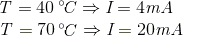
One of the most important types of current loops is the 4 - 20 mA loop. The 4 - 20 mA loop is a common method to transmit sensor information by using current. Normally sensors or transducers are designed to measure a range of values and in many applications there is also a range of values for the measured parameter. For example, suppose a temperature sensor measures the temperature of an industrial process. Temperature must be converted to current in such a way that the temperature measured will be proportional to the current. The current range will be 4 mA to 20 mA. This means that the lowest measured temperature will correspond to 4 mA; the highest to 20 mA. Further, assume that the temperature range that the sensor will measure 40° to 70° C.
In order to transmit a current value proportional to the temperature we need to develop the equation of proportionality. The best and simplest type of equation is a linear equation of the form.
![]()
Where T is the independent variable (temperature) and I is the dependent variable (current). To determine the values of m (the slope) and b (the vertical intersection) we use the two boundary conditions:
Substituting these values in the linear equation:
![]()
![]()
By solving these equations:
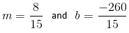
Then the equation is:
![]()
The graph of this equation for the specified range is shown below.

Figure 2. Equation of proportionality of current and temperature.
Configuration
A 4 - 20mA current loop circuit is shown in Figure 3. These current loops are designed using a minimum of four elements.
Transmitter
Normally a sensor or transducer is connected to the transmitter. The sensor measures a physical parameter, such as temperature, pressure, or humidity, and a signal conditioning circuit (part of the transmitter) converts the measured value to an electrical signal such as voltage, current, or resistance. Then the transmitter converts this electrical signal into a current proportional to the measured physical parameter. The transmitter sends this current into the loop.
Wiring
These are the wires used in the loop. It is important to consider them as an element of the loop because they produce a voltage drop, just like any other element in the loop. If the sum of all the voltage drops is bigger than the power supply voltage, the current will not be proportional to the measured parameter and the system will become useless. The wire resistance is normally given in Ohms per unit length, so the total resistance is the product of this value times the length of the wires. The total wiring resistance is represented by the symbol Rw, as is shown in the diagram. The total voltage drop due to the wires is given by Ohm’s law:
![]()
Where I is in amps; is Rw in Ohms; and Vw is in volts.
Power Supply (Compliance Voltage)
This element is responsible for maintaining a stable current in the loop. For a two-wire transmitter (as shown in Figure 2) the power supplies used are always DC. Standard values of 4 - 20 mA loops are 12V, 24V, or 36V. The value chosen by the designer will depend on the number of elements connected in the loop, because the power supply voltage must always be bigger than the sum of all the drops in the circuit, including the wiring drop. There are certain conditions that the compliance voltage should fulfill. Two of the most important are:
- The power supply voltage must be able to power all the devices in the loop, including the wiring voltage drop, when the current is at the maximum current, 20 mA.
- The power supply must be equal or smaller than the maximum voltage rating of any device in the loop.
Receiver or Process Controller
The receiver is a circuit that converts the loop current to a voltage. In general it is simpler to handle and manage voltage than current. After the loop current is generated, it must usually be further processed in a subsequent state of the system. For instance, this current can be used to open or close a valve in order to start or to interrupt a process. It is better to affect the state of the valve with a voltage rather than with a current. This is the reason the process controller or receiver converts the loop current into a voltage. In Figure 3 the receiver is a simple resistor that is an element of the loop. The voltage generated is proportional to the measured physical parameter and it can be used to control a system down the line.
Figure 3 demonstrates how a temperature sensor measures temperature. The sensor is sensing the temperature and sending its value to the transmitter. The transmitter processes the temperature and, using the equation developed above, produces a current proportional to the measured temperature. The loop is powered by one power supply and at the other end of the loop is the process controller where a circuit, in this case a simple resistance, will convert the current to a voltage. This voltage may be used to drive another process. Thus we have a system that translates temperature into voltage using a simple loop.

Figure 3. Typical 4 - 20 mA loop.
The current circulates in the loop. The distance between the sensor-transmitter ensemble and the process controller can be several hundred feet. For instance, the sensor may be sensing temperature in the core of a nuclear reactor and the control room where the process controller is located 2,000 feet or more away.
Applications
A significant advantage of using current instead of voltage to transmit sensor output is that current is the same at any point in a loop. Thus the current in a 4 - 20mA loop will be identical for all of the devices inserted in the loop, as long as the power supply voltage is bigger than the sum of all the voltage drops. Current loops are particularly important when the sensor signal has to be sent to a controller over long distances, since voltage attenuates over the distance it is transmitted.
When current is transmitted there are also voltage losses and attenuation due to the conductors and connected devices. However these voltage drops do not affect the current in the loop, so all devices in the loop receive identical current, provided the power supply has enough power to overcome the sum of all the drops.
Images credits:
Weschler Instruments | IEEE Engineering360


