Noncontact Safety Interlock Switches Information
 Noncontact safety interlock switches are machine safety products that provide a compact, non-contact way to interlock doors, guards, gates, and covers. The switch can be tripped by a simple action such as opening a door. Tripping the switch can turn a machine off, preventing damage to both a human operator and the machine.
Noncontact safety interlock switches work by coupling a moveable door guard with the power source of the hazard. In most applications an interlock is a device used to help prevent a machine from harming its operator or damaging itself by stopping the machine when tripped.
Noncontact safety interlock switches are designed for use in applications where no contact is desired between the switch and actuating key. These switches are suitable for areas with the following requirements:
- High level of protection against tampering
- Extremely hygienic environmental conditions
- Precise door guide not possible
- Machine doors subject to heavy vibration
- High safety category
- Wet, dusty, oily environments
Selection Criteria
There are a number of elements to consider when selecting a noncontact safety interlock switch. These include:
- Purpose of the device
- Level of hazard present at machine
- Severity of possible injury
- Probability of device failure
- Machine stopping time
- Frequency and duration of access
- Performance
Materials
Noncontact safety interlock switches are made of plastic or chemically-resistant steel. Material selection should be based on the ability to withstand all expected and foreseeable stresses. They must comply with safety standards.
Technologies
Noncontact safety interlock switches consist of an actuator, one or more read heads, and a control unit that is connected to multiple power contactors. Each read head transmits an electrical signal or electromagnetic field to the actuator, which processes the data for transmission to the control unit. If the control unit recognizes the transmitted information, the safety outputs are closed. Each actuator includes a uniquely coded element that cannot be reprogrammed.
Example #2 at 1:42 shows a coded magnetic interlock switch.
Video Credit: ABB Electrical Engineering Resource
Most control units provide external device monitoring (EDM) and can be operated in manual- or automatic-start mode. Typically, a control unit manages two or four solid-state outputs and provides individual monitoring of each read head. For applications that require the guarding of more than four doors, control units are connected in series according to safety standards such as EN954-1.
A coded magnetic switch has varying polarity and field strengths to activate the switch. This technology provides a high tolerance to misalignment after sensing.
RFID read heads and actuators provide tamperproof security. A switch's tag can be individually coded to an actuator so no other actuator can be used with it.
Specifications related to these options include:
- Sensing (make) range is the distance between the actuator and the sensing head to activate the relay outputs.
- Break range is the distance between the actuator and the sensing head to deactivate the relay outputs.
Operation
Noncontact safety interlock switches use several types of contacts. Normally closed (NC) and/or normally open (NO) electrical contacts may be used to hold the contacts in one position or the other. Closed contacts can conduct current through the switch, while open contacts cannot conduct current.
|
Positive-break contacts |
Normally closed (NC) electrical contacts which, upon actuation, are forced open by a non-resilient, mechanical drive mechanism. In the event of a mechanical failure such as the breakage of a spring or weld, the contact point remains in an activated position. True spring-actuated safety interlock switches are not considered to be positive-break devices. |
|
Negative operation contacts |
Failsafe switches that are opened by a built-in spring. They should not be used alone in safety operations. |
|
Changeover contacts |
Typically used in single-pole double-throw (SPDT) devices, changeover contacts are a set of three electrical contacts called a pole. Two are fixed and one moves from one to the other. |
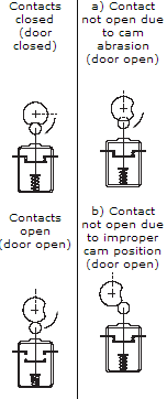
Positive operation switch diagram.
Image Credit: Omron Austrlia Technical Guide
Specifications include:
- The number of normally open and/or normally closed contacts
- Whether or not the switch has positive break contacts
- The maximum current
- The maximum AC voltage
- The maximum DC voltage
Other Features of Noncontact Safety Interlock Switches
- Devices with integral control units can be used to monitor multiple switches.
- Emergency override can be used to override the system.
- Some noncontact safety interlock switches are hermetically-sealed or explosion-proof.
- Products with manual time delays continue to protect equipment even after machine controls are turned off.
- Some switches are tamper-resistant or include a rotating head for multiple entry points.
- A visual indicator can use RFID technology to display a status.
- Operating temperature may play a role in selection in extreme high or low temperature areas.
Standards
Because noncontact safety interlock switches are relied on in potentially hazardous situations, there are many standards that apply to them. Some examples of related standards include:
AENOR UNE-EN 60204-1 — Safety of machinery — electrical equipment of machines — part 1: general requirements (iec 60204-1:2005, modified)
BS EN ISO 14119 — Safety of machinery — Interlocking devices associated with guards — Principles for design and selection
BS EN 60947-5-3 — Low-voltage switchgear and controlgear — part 5-3: control circuit devices and switching elements - requirements for proximity devices with defined behaviour under fault conditions
BS EN 61000-6-3 — Electromagnetic compatibility (EMC) — Part 6-3: Generic standards - Emission standard for residential, commercial and light-industrial environments
BS EN ISO 13849-1 — Safety of machinery — Safety-related parts of control systems Part 1: General principles for design
Agency approval markings and certifications include:
- cULus
- CE
- RoHS
- UL and C-UL listed
- TUV certified