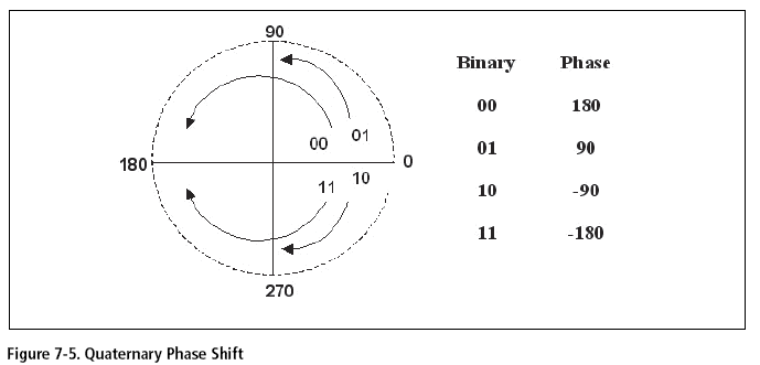
 Rationale
In the fifteen or so years since the first edition of this book, nearly every aspect of data
communications has changed, and above all industrial applications. The original
rationale
for this book was that many people are forced to learn data communications
because the
processes aren't as transparent and as "plug and play" as they should be. Though these
individuals never intended to become experts in data communications, they are nonetheless
now forced to learn some specific detailed facts just to accomplish their primary job functions.
Unfortunately, fifteen years later, there is still a need to understand the technical jargon
and polemics of data communications. Though you will not find it difficult or even tedious
to acquire the necessary knowledge of data communications, the material must be organized
in a way that helps you stay focused on the key points. This edition provides that
framework while also containing significant new material to encompass the changes in
technology and indeed in the direction and focus of industrial applications since the third
edition. Specifically, I have expanded coverage of the different fieldbuses, of industrial
Ethernet and wireless technologies, and of the security considerations that have become
ubiquitous in industrial use.
The need to upgrade the third edition became apparent much as it had with the second
edition: as soon as it was published. The field of data communication is quite dynamic.
Though the fundamentals have not changed (or changed very little) industrial applications
are changing at a quicker pace, and unfortunately, much quicker than the revision cycles of
the texts that hope to cover them. Though much of the previous three editions are still
quite valid, this edition required more than a minor revision, and considerable freshening
was needed to ensure that the materials are not dated.
Objectives
The objectives of the fourth edition are exactly the same as those of the previous ones: to
introduce the principles and applications of industrial data communications and bring you
to a level where you can communicate with other professionals on this topic. Because of
the changes in this field, particularly since the third version, this book assumes you are
familiar with Internet use and perhaps some data communications applications. It is written
in the same conversational style as its predecessors, with the hope that this informality
maximizes your understanding.
Audience
The intended audience is the person with some general technical education who is somewhat
literate with computers. Though knowledge of the electrical-electronic disciplines will
aid understanding, it is still not a prerequisite, as quick (and simplistic) explanations of the
concepts necessary for understanding are given in the appendices. However, as in previous
editions, a willingness to understand new concepts and a sense of historical perspective will
help. As always when reading this text, patience as well as a sense of humor will be found
high on the list of requirements.
Topics
As in all previous versions, the text ranges from simple basics to the complex applications.
A familiarity with basic number systems along with hexadecimal representation is required;
though, here again, these are explained to the necessary level of complexity in the appendices.
As in the third edition, this edition's appendices also cover modulation and
analog/digital conversion fundamentals. For more detail on these subjects, many, many, reference
books, study materials, and computer-assisted training courses are available. This
book is not a design or engineering document but a primer designed to bring your knowledge
quickly up to the current practice. It is not assumed that you already know, or are
even familiar with, the subject of this text, so we discuss concepts and applications only in
the detail needed to grasp general concepts and/or applications.
Larry Thompson
Owner/General Manager
ESdatCo
707 Coleman St.
Marlin, TX 76661