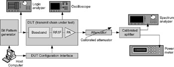
Optimizing and Testing WLANs: Proven Techniques for Maximum Performance

Transmitter tests, during both general design and development as well as for performance testing during design verification, use the following basic setup. Note that there are many variations depending on the exact nature of the test being conducted, but the key pieces of equipment remain more or less the same. The figure below represents this setup in schematic form.
Design engineers almost always construct, test, and optimize each piece of the transmitter chain separately, as it is far easier to find bugs in this manner. However, once the entire transmit chain (baseband, upconverter, and power amplifier (PA)) has been individually verified to function, the pieces are put together into a single module and tested as a unit to verify that performance meets expectations and datasheet specifications. This section deals with such performance tests.
With reference to the figure above, the various elements of the test setup (besides the Device Under Test (DUT)) are:
A bit pattern generator or some other means of driving the baseband device with digital data to be transmitted. In some cases this is accomplished using a PC with a parallel I/O interface, or even a test mode in the actual medium access control (MAC) device that will eventually be used with the transmitter. See a subsequent section in this chapter for methods of forcing the transmitter to generate output data.
A logic analyzer to verify the data that is actually driven.
A calibrated attenuator for reducing...