The Switching Function: Analysis of Power Electronic Circuits

By demonstrating the usefulness of the switching function in analyzing power electronic circuits, this text derives compact expressions for output voltage and current and input current.
The analysis of the rectifier with capacitive load is a classical case of a 'circuit determined' switching function. The switching instances are circuit determined and they must be known before the application of the technique.
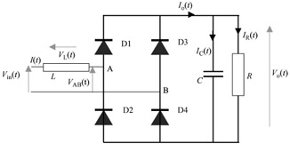
The analysis is based on the input loop equation. The voltage at the input of the bridge is made up from two components each at a different time slot: the input supply voltage and the 'reflection' of the output dc voltage. For this purpose two switching functions are introduced, both circuit determined (Fig. 5.1).
The output voltage ripple is ignored when the line current is calculated; it makes the derivation simpler. This is justified for a practical system where large capacitors are used. The output ripple voltage itself is later calculated in terms of the output ripple current. The line current is derived as a function of the parameters of the two switching functions, the output dc voltage and the other circuit parameters.
The output dc voltage is calculated from the expression of the line current by considering the two points in time where it is zero.
The mathematical modelling of this circuit is a good candidate for the procedure outlined in Chapter 1 for the application of the switching function technique. The analysis of this circuit is based on the input loop voltage expression. The input loop comprises the input voltage V in( t), the voltage across the...