The Switching Function: Analysis of Power Electronic Circuits

By demonstrating the usefulness of the switching function in analyzing power electronic circuits, this text derives compact expressions for output voltage and current and input current.
The three-phase full-wave phase controlled rectifier is analysed in this chapter by considering an R-L load and continuous conduction. Voltage and current expressions, frequency spectrum, power and distortion factors are derived using the switching function. The overlap is dealt with in the next chapter in order to derive expressions for the output voltage 'notches'. In both cases the relevant switching functions are identified.
The various modes of the circuit are set by the switching action of the six thyristors; the voltage and current at any point is set by the mode of the circuit. In deriving the switching functions a careful study of the action of the semiconductor switches is required. This is done by developing the modes of the circuit, Fig. 7.1. We identify three switching functions that contribute to the output voltage, one for each line voltage: F ry( t), F yb( t) and F br( t). The switching functions are of the quasi-square shape expressed as a sum of cosines and they are phase displaced between them by 60 . The delay firing angle ? is measured in the normal way from the positive going crossing of the red phase voltage.
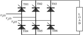
Six Modes are identified as shown in Fig. 7.2; the overlap is neglected. During any mode two thyristors are conducting, one from the upper group...