The design of the CNN circuit implementing the CNN motor-neuron (2.5) is now introduced. The circuit is based on operational amplifiers and RC components. Starting from this circuit and applying standard techniques for switched-capacitor design [Gregorian and Temes (1986); Johns and Martin (1997)] the switched-capacitor circuit discussed in Sec. 3.5 can easily be derived.
Equations (2.5) are dimensionless. We first consider a model suitable for the circuit implementation. The equations of the CPG cell including the time-scaling factor are the following:
| (B.1) | 
|
with
| (B.2) | 
|
and ?=RC. In this model the state variables are represented by voltages.
The core of our circuit is the Miller integrator/adder block [Smith and Sedra (1998)] shown in Fig. B.1. The equation it implements is the following:
| (B.3) | 
|
where x is the voltage across the capacitor C 1. Equation (B.3) perfectly matches that of a CNN first-order cell. y i and y j represent the outputs of two generic cells. The piece-wise linear output (B.2) is obtained by considering an inverting block and exploiting the saturation of the operational amplifier (i.e. choosing the gain to saturate the output). This approach leads to saturation points depending on the voltage supply values. These saturations are then scaled to the standard values 1. Therefore the values of the resistances of the CNN circuit depend on the voltage supply. The whole CNN implementing the CNN neuron is shown in Fig. B.2.
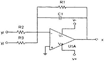 Fig. B.1: The Miller integrator is the core of the CNN circuit.
 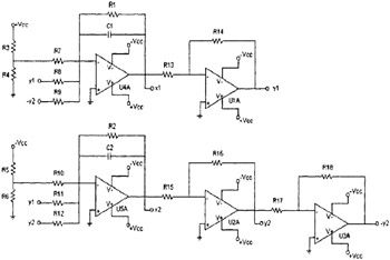 Fig. B.2:
Copyright World Scientific Publishing Co. Pte. Ltd. 2004 under license agreement with Books24x7


 TABLE OF CONTENTS