Analysis and Control of Linear Systems

A collection of articles by engineers and mathematicians, this book is about the theory of continuous-state automated systems whose inputs, outputs and internal variables can vary in a continuous manner.
Chapter written by Houria SIGUERDIDJANE and Martial DEMERL .
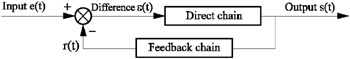
The block diagram of any closed loop control system (Figure 9.1) consists of an action chain and of a reaction (or feedback) chain which makes it possible to elaborate an error signal ?( t), the difference between the input magnitude e( t) and the measured output magnitude r(t). The output of the system is s(t).
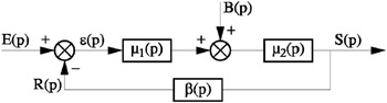
When the system is subjected to interferences b( t), its general structure is represented by Figure 9.2 by supposing that its working point in the direct chain is known. We designate by E( p), R(p), ? (p) and S(p) the Laplace transforms of the input, the measurement, difference and the output respectively (see Figure 9.2).
The open loop transfer function of this chain is the product of transfer functions of all its elements; it is the ratio:
The closed loop transfer function of this chain is the ratio ![]() with:
with:
We have:
and:
by using equation [9.2] and by eliminating R(p) and ?(p) of equations [9.3] and [9.4], we obtain:
When the interferences are zero, B(p) = 0, the transfer function of the looped system is then:
or simply:
by supposing that ?(p) = 1 (p) 2 ( p ).
The transfer function with respect to...