Overview
This chapter describes how GNSS user equipment processes the signals from the satellites to obtain ranging measurements and then a navigation solution. It also reviews the error sources and describes the geometry of the navigation signals. It follows on from the fundamentals of satellite navigation described in Section 6.1.
Different authors describe GNSS user equipment architecture in different ways [1 4]. Here, it is divided into four functional blocks, as shown in Figure 7.1: the antenna, receiver hardware, ranging processor, and navigation processor. This approach splits up the signal processing, ranging, and navigation functions, matching the different INS/GNSS integration architectures described in Chapter 12.
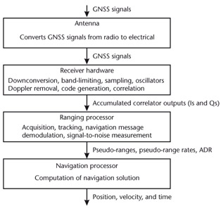 Figure 7.1: GNSS user equipment functional diagram.
 Section 7.1 describes the geometry of satellite navigation, covering the satellite position and velocity, range and range rate, line of sight, azimuth and elevation, and navigation solution geometry. Section 7.2 describes the antenna and receiver hardware, with an emphasis on signal processing. Section 7.3 describes the ranging processor, including acquisition, code and carrier tracking, lock detection, navigation message demodulation, signal-to-noise measurement, and generation of the pseudo-range, pseudo-range rate, and carrier-phase measurements. Section 7.4 discusses the error sources leading to ranging errors, including ephemeris and satellite clock errors, ionosphere and troposphere propagation errors, tracking errors, and multipath. The satellite clock, ionosphere, and troposphere errors are partially corrected by the user equipment, within either the ranging processor or the navigation processor. Finally, Section 7.5 describes the navigation processor, covering both single-point and filtered navigation solutions, discussing integrated navigation and tracking, and...