RF and Baseband Techniques for Software Defined Radio

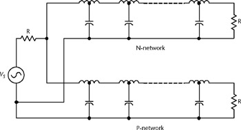
The general structure of a passive broadband 90 splitter network, based upon an all-pass filter configuration, is shown in Figure A.1. Its transfer function is of the form:
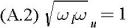
where the total network complexity of both the N and P networks is n. The values for for the N and P networks are tabulated in Tables A.1 to A.8. The values in these tables are normalised such that:
| Filter Order, n | Phase Ripple (Degrees) | ? N | ? P |
|---|---|---|---|
| 6 | 6.84 | 43.3862 | 8.3350 |
| 2.0264 | 0.4935 | ||
| 0.1200 | 0.0231 | ||
| 8 | 2.12 | 59.7833 | 14.4159 |
| 4.8947 | 1.6986 | ||
| 0.5887 | 0.2043 | ||
| 0.0694 | 0.0167 | ||
| 10 | 0.66 | 75.8845 | 20.4679 |
| 8.3350 | 3.5631 | ||
| 1.5279 | 0.6545 | ||
| 0.2807 | 0.1200 | ||
| 0.0489 | 0.0132 |
| Filter Order, n | Phase Ripple (Degrees) | ? N | ? P |
|---|---|---|---|
| 6 | 4.99 | 34.3132 | 7.0607 |
| 1.9111 | 0.5233 | ||
| 0.1416 | 0.0291 | ||
| 8 | 1.39 | 47.0857 | 11.8249 |
| 4.3052 | 1.6253 | ||
| 0.6153 | 0.2323 | ||
| 0.0846 | 0.0212 | ||
| 10 | 0.39 | 59.6517 | 16.5238 |
| 7.0607 | 3.2112 | ||
| 1.4749 | 0.6780 | ||
| 0.3114 | 0.1416 | ||
| 0.0605 | 0.0168 |
| Filter Order, n | Phase Ripple (Degrees) | ? N | ? P |
|---|---|---|---|
| 4 | 13.9 | 16.8937 | 2.4258 |
| 0.4122 | 0.0592 | ||
| 6 | 3.43 | 27.1337 | 5.9933 |
| 1.8043 | 0.5542 | ||
| 0.1669 | 0.0369 | ||
| 8 | 0.84 | 37.0697 | 9.7136 |
| 3.7944 | 1.5566 | ||
| 0.6424 |