This chapter is an introduction to analog and digital filters. It begins with the basic analog filters, transfer functions, and frequency response. The magnitude characteristics of Butterworth and Chebychev filters and conversion of analog to equivalent digital filters using the bilinear transformation is presented. It concludes with design examples using MATLAB and Simulink when applicable,
11.1 Filter Types and Classifications
Analog filters are defined over a continuous range of frequencies. They are classified as low-pass, high-pass, band-pass and band-elimination (stop-band), The ideal magnitude characteristics of each are shown in Figure 11.1. The ideal characteristics are not physically realizable; we will see that practical filters can be designed to approximate these characteristics.
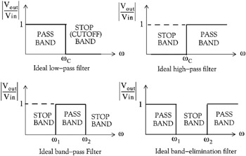 Figure 11.1: Magnitude characteristics of the types of filters
 Another, less frequently mentioned filter, is the all-pass or phase shift filter. It has a constant magnitude response but is phase varies with frequency. Please refer to Exercise 4, Page 11 94, at the end of this chapter.
A digital filter, in general, is a computational process, or algorithm that converts one sequence of numbers representing the input signal into another sequence representing the output signal.
Accordingly, a digital filter can perform functions as differentiation, integration, estimation, and, of course, like an analog filter, it can filter out unwanted bands of frequency.
Analog filter functions have been used extensively as prototype models for designing digital filters and, therefore, we will present them first,

 TABLE OF CONTENTS