Signals and Systems with MATLAB Computing and Simulink Modeling, Third Edition

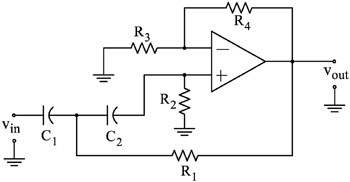
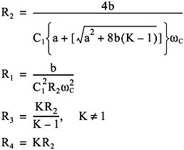
| Q: | 1. The op amp circuit below is a VCVS second-order high-pass filter whose transfer function is ![]() and for given values of a, b, and desired cutoff frequency ? c, we can calculate the values of C 1, C 2, R 1, R 2, R 3, and R 4 to achieve the desired cutoff frequency ? c. ![]() For this circuit, ![]() and the gain K is Using these relations, compute the appropriate values of the resistors to achieve the cutoff frequency f c=1 KHz. Choose the capacitors as C 1=10/f c ?F and C 2=C 1. Plot G(s) versus frequency. Solution using MATLAB is highly recommended. |
|
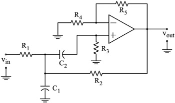
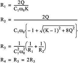
| Q: | 2. The op amp circuit below is a VCVS second-order band-pass filter whose transfer function is ![]() Let ? 0=center frequency, ? 2=upper cutoff frequency, ? 1=lower cutoff frequency, Bandwidth BW= ? 2 ? ? 1, and Quality Factor Q= ? 0/BW We can calculate the values of C 1, C 2, R 1, R 2, R 3, and R 4 to achieve the desired centered frequency ? 0 and bandwidth BW. For this circuit, ![]() Using these relations, compute the appropriate values of the resistors to achieve center frequency f 0=1 KHz, Gain K=10, and Q=10. Choose the capacitors as C 1=C 2=0.1 ?F. Plot G(s) versus frequency. Solution using MATLAB is highly recommended. |