Structural Steel Designer's Handbook, 3rd Edition

Use this comprehensive, A-Z guide to find a wealth of practical techniques for cost-effectively designing steel structures, from buildings to bridges.
 TABLE OF CONTENTS
 To illustrate the design procedure, a two-lane highway bridge with simply supported, composite, plate-girder stringers will be designed. As indicated in the framing plan in Fig. 12.13a, the stringers span 100 ft c to c of bearings. The typical cross section in Fig. 12.13b shows a 26-ft roadway flanked by 1-ft 9-in-wide barrier curbs. Structural steel to be used is Grade 36. Loading is HS25. Appropriate design criteria given in Sec. 11 will be used for this structure. Concrete to be used for the deck is class A, with 28-day strength f ? c = 4,000 psi and allowable compressive stress 0.4 f ? c = 1600 psi. Modulus of elasticity E c = 3,600,000 psi.
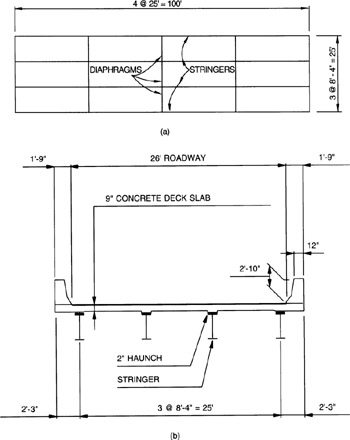
Assume that the deck will be supported on four plate-girder stringers, spaced 8 ft 4 in c to c, as indicated in Fig. 12.13.
Concrete Slab. The slab is designed, to span transversely between stringers, in the same way as for rolled-beam stringers (Art. 12.2). A 9-in-thick one-course, concrete slab will be used with the plate-girder stringers.
Stringer Design Procedure. The general design procedure outlined in Art. 12.2 for rolled beams also holds for plate girders. In this example, too, only a typical interior stringer will be designed.
Loads, Moments, and Shears. Assume that the girders will not be shored during casting...
