MSP430 Microcontroller Basics

Using both C and assembly language, this book combines a tutorial approach with a description of the CPU and main peripherals that builds from a basic program for lighting LEDs to the use of a timer.
 TABLE OF CONTENTS
 There are two SAR ADC modules available on the MSP430, the ADC10 and ADC12. The obvious distinction is the number of bits, which is given in their names, and there are several other differences. The ADC12 has a more elaborate set of registers for storing batches of results. It needs external capacitors on its voltage reference but the ADC10 does not (in fact it must not). Interrupts are more complicated in the ADC12 as well. I concentrate on the simpler ADC10 and describe the differences briefly in the section "The ADC12 Successive-Approximation ADC" on page 432.
Figure 9.16 shows a simplified block diagram of the ADC10 in the F20x2; there are more inputs in larger devices. As in the case of Comparator_A+, the module looks more complicated than you might expect because of the wide range of options. I omit the connections for external references, automatic sequences of conversions, and the data transfer controller to avoid obscuring the central features, which I now describe. These are controlled in the usual way by the registers ADC10CTL0 and ADC10CTL1. Most features can be configured only while the enable conversion bit ENC is clear to ensure that the ADC is inactive.
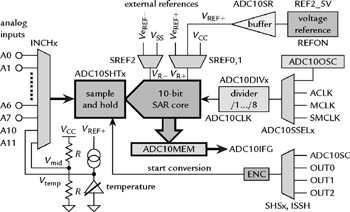
At the heart of the ADC10 is a 10-bit, switched-capacitor, SAR core. It is...