MSP430 Microcontroller Basics

Using both C and assembly language, this book combines a tutorial approach with a description of the CPU and main peripherals that builds from a basic program for lighting LEDs to the use of a timer.
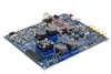
I do not describe the ADC12 in detail because it works on the same principles as the ADC10. However, some aspects of its operation are different and I pick these out. Finally, I show a simple example with the TI MSP430FG4618/F2013 Experimenter's Board.
The successive-approximation core and the choices of inputs, clocks, and triggering sources are much the same as the ADC10. The same selection of reference voltages is available but are implemented differently. Here are the principal distinctions between the ADC12 and ADC10:
The output has 12 bits rather than 10. That is obvious but this is a good place to remind you about the importance of good analog design to avoid noise and errors if you want the lower bits to be meaningful.
The higher precision places a stricter requirement on the sampling time as well, which should be extended to 9 ?. Also, the input capacitance is higher at 40pF.
The internal voltage reference requires an external storage capacitor. This takes a long time to charge after the reference has been turned on and 17 ms should be allowed for the voltage to stabilize. That's milliseconds, not microseconds as for the reference and buffer in the ADC10. The capacitor is not required if you use V SS and V CC as references.
The sampling time can be controlled in two ways. The first, called pulse mode, is the same as in the ADC10 with a selected number...