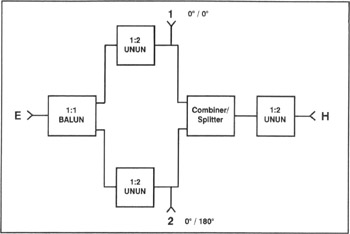
Transmission Line Transformers, Fourth Edition

Chapter 17: Notes on Power Combiners and Mixer Transformers

Sec 17.1: Introduction

Two common uses of transformers are in power combiners/splitters and diode double-balanced mixers. Because these circuits typically use transformers with bifilar or trifilar windings wound on ferrite toroidal or binocular cores, they are often described as "transmission line transformers" without regard to the actual transformer operation. This chapter provides a descriptive analysis of these circuits to show how they use the flux linkages of conventional transformers rather than transferring the signal from an input to an output by transmission line modes, and are not transmission line transformers.

Sec 17.2: Power Combiners and Splitters

A power combiner/splitter is either a combiner or a splitter, depending upon the direction the source of power takes. In one direction, it sums multiple sources into a common output; in the other direction, it divides a single source into multiple outputs. Fig 17-1 shows a block diagram of a popular logic circuit. If power is applied to terminal H on the right, then half of the power will appear at terminals 1 and 2. Also, the voltages will have the same phase as the source (1=2). Terminal E is isolated from the rest of the circuit because of the choking action of the balun. In-phase (common mode) currents are suppressed. This circuit is an RF version of the classic telephone hybrid.


Figure 17-1: Block diagram of a popular logic circuit.

If power is applied to terminal E, then half of the power will appear at terminals 1 and 2. But in this case,...

UNLIMITED FREE
ACCESS
TO THE WORLD'S BEST IDEAS

SUBMIT
Already a GlobalSpec user? Log in.

This is embarrasing...

An error occurred while processing the form. Please try again in a few minutes.

Customize Your GlobalSpec Experience

Category: Fiber Optic Couplers
Finish!
Privacy Policy

This is embarrasing...

An error occurred while processing the form. Please try again in a few minutes.