Attenuators
Many times we are faced with the problem of needing a particular voltage for an application but the signal generator (or any other source) will not produce the desired voltage level. To solve this dilemma normally we could use a voltage attenuator using two resistors. The exact value of the resistors is not important because the level of the voltage can be adjusted using the signal generator amplitude control and the ratio of the two resistors.
When using the signal generator to apply a voltage to an energized circuit, a capacitor must be placed between the signal generator and the circuit to block the circuit voltage from affecting the signal generator.
Figure No. 1.1 shows an attenuator. The voltage across R2 (V2) could be applied to a circuit. This can be made to be of any value between the source voltage (Eg) and zero1.
By applying the voltage divider rule to this circuit we obtain
 (1.1)
(1.1)
Eq. 1.1 is the attenuated voltage of the source (Eg in this case). Notice that by choosing appropriate values for R1 and R2 the ratio (fraction)
 (1.2)
(1.2)
can have a range between 0, when R2 = 0 or when R1 = ∞, and 1.0, when R1 = 0 or when R2 = ∞. Therefore, V2 can be made to
have a value between Egand 0. If we keep the value of R1 constant, then V2 will depend only on R2 and Eg.
1 If, in theory, you replace R2 by a short circuit.
Meter Loading
When a measuring device is used to measure a value in a circuit (current or voltage) its impedance affects the measured value.
This is very similar to the Uncertainty Principle of Heisenberg in Quantum Physics. According to this principle2, “it is impossible to specify precisely and simultaneously the values of both members of particular pairs of physical variables that describe the behavior of an atomic system. In the Hamiltonian sense the members of these pairs of variables are canonically conjugate to each other”. Or,
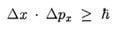
where ћ = h/2π, and h is Planck’s constant. (If you do not understand this statement, ask your lab instructor!)
This concept is called meter loading. The impedance of the measuring device changes the impedance of the circuit where the measurement is taking place. Thus, when applying the meter to the circuit to do the measurement, the circuit impedance (and thus the current and voltage) will change according to the value of the meter impedance. In order to diminish the meter effect when measuring a voltage in a circuit, the impedance of the meter should be very large3 with respect to the impedance across the measuring points4.
In general, the oscilloscope has an impedance of the order of 10 MΩ when using the X10 probe, and an impedance around the 1 MΩ when using the X1 probe. Each oscilloscope, however, has different impedances. The reader should get this information about the level of these impedances by reading the manufacturer specifications of the oscilloscope and/or the probes available in the laboratory setting.
The VOMs, as well, have impedances that depend on the mode of operation. The level of impedance (or resistance) is different when measuring AC and DC voltages. When using a VOM in the laboratory, the reader should consult to the specifications of the instrument.
How to measure voltages with an oscilloscope:
To measure the voltage between two points in a circuit using the oscilloscope, the reader should follow one of the following two rules according to the measurement being made:
One of the points is ground – When measuring a voltage between point a and ground, just connect the connector cable from point a to channel 1 (or any other channel) of the oscilloscope. Because every channel of the oscilloscope is grounded, this procedure will give you the voltage between point a and ground.
Neither point is ground – If neither point a or point b is ground, then proceed as follows:
- Connect channel 1 of the oscilloscope to point a5.
- Connect channel 2 of the oscilloscope to point b.
- Set the oscilloscope on the ADD feature.
- Set channel 2 to the invert feature.
- Make sure that the vertical sensitivity controls of both channels (volts/div) are in the same position6.
Following this procedure, we are actually measuring the voltage Vab between points a and point A using the following known equation:
where Vaand Vb are the voltages from a to ground and from b to ground respectively.
2 One of the most extraordinary and important achievements since the beginning of history.
3 Why? Answer this question in your lab report.
4 Normally we take the rule of thumb that the impedance of the meter should be at least ten times larger than the impedance in parallel with the measuring device.
5 Note that point a and point b can be any of the two points.
6 This should always be the case when using the ADD feature of the oscilloscope.
© 2024 GlobalSpec, Inc.
 This book is designed for students who are taking their first course in analog electronics in either a two-year or four-year program. The prerequisites are a DC-AC course; a basic knowledge of algebra, including the ability to solve simultaneous linear equations; and a strong knowledge of trigonometry. The main topics in this book provide an introduction to the most important semiconductor devices: how they are built, how they operate, and how they are used in larger electronic modules.