Digital-to-Analog Converters Information
Digital-to-analog converters produce an analog output which is proportional to a digital input. They perform the opposite function to that of analog-to-digital converters.  Digital-to-analog converters (DAC) convert digital signals, comprised of "words" made up of binary values, into analog signals. DACs are used in conjunction with analog-to-digital converters (ADC) in a number of common applications.
For example, control systems often rely on analog control signals but may also require signal processing at various system points. These systems often accept an analog input from a device, convert it to a digital signal using an ADC, condition or
change the signal using a microprocessor, then convert the digital signal back to an analog output using a DAC.
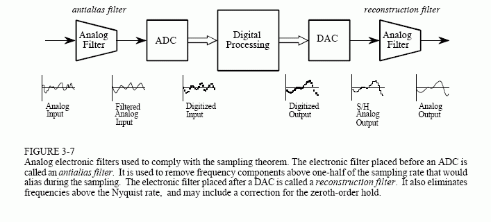
The image below illustrates the use of an ADC, a DAC, and a pair of filters in a digital signal processing (DSP) application. Because processing must be done using digital methods, an ADC is required to convert the analog signals into digital equivalents, and a DAC is needed to convert the processed signals back to analog for compatibility with analog devices. As noted, the filters eliminate harmonic frequencies above the Nyquist frequency and correct other errors inherent in signal conversion.

Diagram describing DSP in accordance with the sampling theorem. Image credit: Steven W. Smith / California Technical Publishing
Digital-to-Analog Conversion
The relationship between a digital signal and its analog counterpart can be described by the following formula, which is dependent on the device's resolution in bits. In the case of a 3-bit DAC, the formula is:
e258d79d199e45b7b15a7852e5a7ffb8.gif)
where:
VDAC = analog voltage
K1 = scale factor (ratio between the digital and analog signals)
bn = nth converter bit
VREF = reference voltage
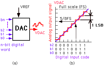
For example, by plugging in the binary word 101 for a device with a scale factor of 1 and a reference voltage of 5 V (the peak of the analog signal's range), the result would be 5/8 multiplied by 5, or 3.125 V.
The image below shows the input-output characteristics of the same 3-bit DAC. On the graph at right, each binary input represents a sampling point. These values are used to form a digital signal, which is then converted to a "smoother" analog signal by using an analog filter.

Image credit: University of Pennsylvania
Zero-Order Hold
An immediate difference between digital and analog signals is time. Digital signals are discrete-time signals, meaning they output a sequential series of values, while analog signals are continuous-time with continuous (non-discrete) domains. In order to reconstruct a signal, a typical DAC will latch binary information for a full sample period using a clock signal; this is the reason that digital signals appear as stair-like lines when graphed. Therefore, a low-pass reconstruction filter must be employed to eliminate extraneous harmonics and smooth the signal to render it suitable for output.
Sampling

Sampling in digital-to-analog conversion shares similar formulas with analog-to-digital operations. DAC sampling presents some unique challenges, however.
A major issue introduced when sampling a digital signal is quantization error (also known as distortion), which results from having multiple inputs (binary bits) for a single output value. Quantization is frequently caused by rounding precise values to the next closest integer, causing distortion of the reconstructed signal. While quantization is a natural occurrence in DAC operation, it can be minimized by using high-resolution devices, since increasing the number of bits increases the gradation scale of the signal.
Resolution
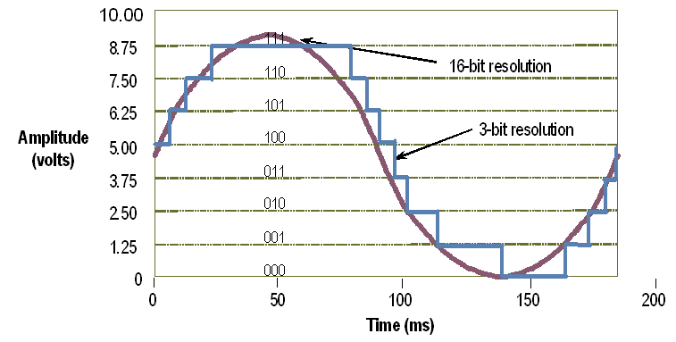
DAC precision is determined by the number of bits the device possesses. The number of bits, n, is directly related to the number of sampling gradations, N, so that N = 2n. (Gradations can be thought of as the scale of measured intervals which express values contained in the signal to be converted.)
For example, a 12-bit converter is capable of 4096 gradations. If the output signal is within the range of 0-5 V (a typical control signal), this range would be broken up into 4096 intervals in order to match analog or digital values, with 0 V being 0 and 5 V being 4095. If the amplitude of the digital signal is 2000 at a given sample time, the analog output would be 2.4414 V. The entire digital signal can be mapped proportionally using these gradations.
Device precision can be defined as 1/N, with smaller values indicating greater precision. For example, a 4-bit converter has a precision 1/16 that of the original signal, while a 10-bit one is 1/1024 as precise.

A sine wave translated using 16-bit (purple) and 3-bit (blue) resolutions. The 16-bit device is capable of 65,528 more gradations than the 3-bit one, resulting in a much more accurate signal. Image credit: National Instruments
Design
Digital-to-analog converters may use one or several methods (in the case of hybrid devices) for converting a digital signal. Some of the most common are described in the table below.
|
Type |
Description |
Characteristics |
|
Pulse-width modulator |
Uses an internal clock to repeatedly count up and down for varying time periods; average of times determines analog output. |
Simplest type; widely used in electric motor control, DC power control, and audio conversion. |
|
Oversampled |
Employs a 1-bit DAC sampled at frequencies significantly higher than Nyquist frequency; necessitates using both a high- and low-pass filter to remove noise. |
High resolution and frequency; low-noise; oversampling techniques result in high performance with relaxed component capabilities. |
|
Binary-weighted |
Uses separate components (resistors, capacitors, or current sources) for each DAC bit; typically <10-bit resolution. |
Expensive to manufacture; extremely fast; poor accuracy. |
|
R-2R ladder |
Binary-weighted subtype; uses cascading resistors with values R and 2R. |
Less expensive than typical binary-weighted types; extreme precision is necessary to eliminate distortion; limited to low resolutions. |
|
Hybrid |
Uses a combination of above methods; may use one method per individual bit. |
Eliminates deficiencies of individual methods. |
Standards
DACs may be manufactured and used in accordance with published standards and specifications. Example standards are listed below.
-
SMD 5962-11208 11-bit CMOS digital-to- analog converter
- IEEE 1658 Terminology and test methods of digital-to-analog converter devices
- MIL-C-62207B Circuit card assembly: Digital- to-analog converter
References
Steven W. Smith, The Scientist and Engineer's Guide to Digital Signal Processing, ADC and DAC (book chapter).
Image credits:
Acromag, Inc. | California Technical Publishing | OMEGA Engineering, Inc. | University of Pennsylvania | Omega Engineering | National Instruments
