Advanced Systems Design with Java, UML and MDA

In this chapter we complete the introduction of UML notation by describing the modelling languages used to define dynamic behaviour of a system: statecharts (also called state machines), collaboration and sequence diagrams.
In contrast to class diagrams, statecharts focus on the dynamic behaviour of objects, and graphically represent the life history of objects over time and their patterns of inter-communication.
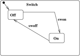
Figure 4.1 shows a simple statechart with two states, On and Off and transitions between them.
The elements of a statechart are:
States Written as rounded-corner boxes, these have a name.
Transitions Written as arrows from one state, the source of the transition, to another, the target, they are labelled with the event that causes the transition.
Default initial state The state the object is in at the start of its life history, indicated as the target of a transition arrow with source the initial pseudostate (a black filled circle).
Termination of a statechart can be shown by a 'bullseye' symbol.
UML divides statecharts into two kinds:
Protocol state machines, which describe the allowed life histories of objects of a particular class. In this case the events on transitions correspond to operations of that class, and transitions may have pre and post conditions (in addition to any that are defined in the class diagram: implicitly the transition precondition is conjoined to that of the operation, for the given starting state. Likewise for the postcondition). Transitions cannot...