Switchmode RF Power Amplifiers

Switching mode RF amplifiers have become a hot area of RF/wireless design. This book explores both the theory behind switching mode RF amplifiers and design techniques for them.
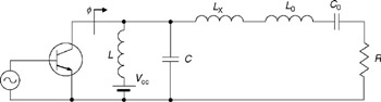
The basic circuit of a switched-mode subharmonic Class-E power amplifier is shown in Fig. 6.7. The load network consists of a parallel inductance L, a shunt capacitance C, a series Lo Co-resonant circuit tuned on the fundamental, and a load R. The condition of a subharmonic tuning implies that the inductance L resonates with the capacitance C at half a fundamental frequencyf 0 In this case, to provide an inductive reactance at the fundamental frequency seen by the device collector, it is necessary to include a series inductance L x. Hence, the first unknown parameter q can be set to
The coefficients C 1 and C 2 are determined from
Then, the other two parameters ? and p can be found by applying the optimum Class-E condition given by Eqs. (6.1) and Eqs. (6.2) to Eq. (6.45) and using Eqs. (6.64) and Eqs. (6.65) as
Fig. 6.8 shows the normalized collector (a) voltage and (b) current waveforms for idealized optimum subharmonic Class-E mode. From collector voltage and current waveforms it follows that, when the transistor is turned on, there is no voltage across the switch, and current i((ot) consisting of the load sinusoidal and inductive current flows through the device. The collector voltage and current waveforms are very similar to those of a Class E with shunt capacitance.
As a result, for a...