PIC Microcontrollers: Know It All

Featuring a presentation of theory, hard fact, and project-based direction, this reference will help average embedded engineers working with PIC microcontrollers solve a variety of real-life problems in this area.
Now that the basic programming methods have been introduced, we can look at some more advanced techniques. Sample programs demonstrating use of the timer, interrupts and data table are included in this chapter.
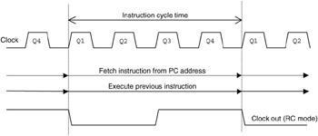
The microcontroller program execution is driven by the clock signal generated by an internal oscillator whose frequency is controlled by either an external RC or crystal (XT) network. This signal is divided into four internal clocks (Q1 Q4) which run at a quarter of the oscillator frequency (F OSC/4). These provide four separate pulses during each cycle to trigger the processor operations. These include fetching the instruction code from the program memory, and copying it to the instruction register. The instruction code is then used by the decoder to set up the control lines to carry out the required process. The four clocks are used to operate the data gates and latches within the MCU to complete the data movement and processing.
This instruction timing is illustrated in Fig. 6.1. Note that, if the CR clock option is used, an output instruction clock signal at F OSC/4 is available at the CLKOUT pin to operate external circuits synchronously. It can also be used in hardware testing to check that the clock is running, and to measure its frequency.
The result of this clocking scheme is that each instruction takes four clock cycles to execute, unless a jump (GOTO or CALL) occurs. These will take eight clock cycles, because...