PIC Microcontrollers: Know It All

Featuring a presentation of theory, hard fact, and project-based direction, this reference will help average embedded engineers working with PIC microcontrollers solve a variety of real-life problems in this area.
A control program usually requires more than turning outputs on and off. They switch on and off because an event has happened. This event is then connected to the input of the microcontroller to "tell" it what to do next. The input could be derived from a switch or it could come from a sensor measuring temperature, light levels, soil moisture, air quality, fluid pressure, engine speed, etc. In this chapter we will concern ourselves with digital on/off inputs. As an example let us design a circuit so that switch SW 1 will turn an LED on and off. The circuit diagram is shown in Fig. 11.1. This circuit uses the 16F84 microcontroller with a 32-kHz crystal.
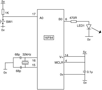
It can of course also be performed with any of the microcontrollers discussed previously, including the 16F818 using its internal oscillator, in which case the crystal and 2 68pF capacitors are not required.
The program to control the hardware would use the following steps:
Wait for SW1 to close.
Turn on LED1.
Wait for SW1 to open.
Turn off LED1.
Repeat.
In the circuit diagram SW1 is connected to A0 and LED1 to B0. When the switch is closed A0 goes low or clear, so we wait until A0 is clear. The code for this is:
BEGIN BTFSC PORTA,0 (test bit 0 in file PORTA skip if clear) GOTO...