Applied CATIA V.5 R15

Providing step-by-step instruction with numerous illustrations, this book offers a self-guided learning experience for users to learn CATIA V.5 R15 on their own with little or no outside help.
Objectives:
Design multiple sketch parts
Learn to use the X, Y, and Z Planes
Learn to use the Wireframe viewing command
Learn to project geometry on to a new sketch
Learn to use the Shell command
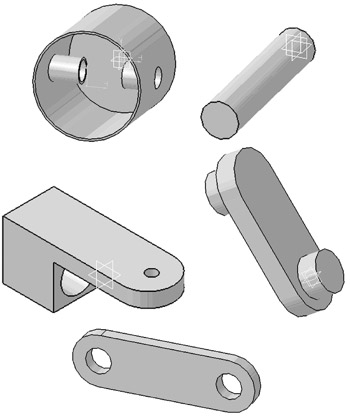
Chapter 6 includes instruction on how to design the parts shown below.
Start CATIA by referring to "Chapter 1 Getting Started".
After CATIA is running, begin a new sketch.
Move the cursor to the upper left corner of the screen and left click on the Circle icon as shown in Figure 1.
Move the cursor to the center of the screen and left click once. This will be the center of the circle as shown in Figure 2.
Move the cursor to the right and left click once as shown in Figure 3.
Move the cursor to the middle left portion of the screen and left click on the Constraint icon as shown in Figure 4.
Move the cursor over the edge of the circle causing it to become dashed. Left click once. The dimension will be attached to the cursor.
Move the cursor down. The actual dimension of the line will appear as shown in Figure 6.
Move the cursor to where the dimension will be placed and left click once. While the dimension is still dashed, double left click. The Constraint Definition dialog box will appear as shown in Figure 7.
To edit the dimension, type 50 in the Constraint Definition dialog box (while the current dimension is highlighted)...