Fundamentals of High-Frequency CMOS Analog Integrated Circuits
4.3: Cascaded Tuned Stages and the Starggered Tuning

4.3 Cascaded Tuned Stages and the Starggered Tuning

The voltage gain of a tuned amplifier in the s-domain was given as


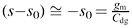
From Fig. 4.14(a) it can be seen that in the vicinity of the resonance frequency and for s 0 ? s p1, ( s ? s p2) 2 s and . Therefore (4.38) can be simplified as


and with A v( ? 0) = ? g m R eff and Q eff = ? 0 CR eff,


If n identical stages are connected in cascade, the total voltage gain becomes


and the bandwidth of the amplifier shrinks to


This is the appropriate solution if a high-gain and narrow-band amplifier is needed. But in some cases a relatively broad bandwidth and a flat frequency characteristic in this band are needed. It can be understood intuitively that tuning the stages of this multi-stage amplifier to slightly different frequencies around the center frequency of the band can lead to a feasible solution. In this case the gain of this multi-stage amplifier can be written as


which has n poles.

The appropriate positions of the poles of the transfer function (the voltage gain in our case) to obtain a desired frequency characteristic are investigated in depth in classical filter theory [28]. It is known that the number of poles and their relative positions determine the bandwidth and the shape of the frequency characteristics. Among several possibilities for...

UNLIMITED FREE
ACCESS
TO THE WORLD'S BEST IDEAS

SUBMIT
Already a GlobalSpec user? Log in.

This is embarrasing...

An error occurred while processing the form. Please try again in a few minutes.

Customize Your GlobalSpec Experience

Category: IC Electronic Filters
Finish!
Privacy Policy

This is embarrasing...

An error occurred while processing the form. Please try again in a few minutes.