Introduction to Structural Dynamics

| Q: | 4.1 (a) Reconsider the beam of Figure 4.5. At the free end of that two-beam-element beam, add a third massless beam element of length L and double stiffness values exactly like that of the inboard beam. Like that previously inboard beam element, let the new beam element also be clamped at its outer end so that the new three-element beam model is clamped at both its outer ends. Write the new stiffness matrix. (b) If the lumped masses of the structure pictured in Figure 4.5 are unaltered by the addition of the third beam element as in part (a), does the mass matrix change? Does the applied load vector change? (c) What changes in the analysis would be necessary if the BC at the base of the frame of Figure 4.6 were changed from those of fixed beam ends to simply supported beam ends? |
|
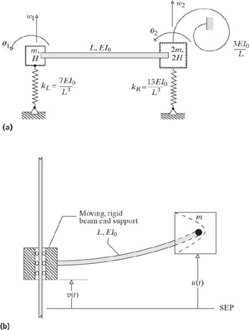
| Q: | 4.2 (a) The one-beam, three-spring system shown in Figure 4.11(a) is undergoing small, force free vibrations. ( Force free vibrations means that the system was set into motion at time zero and, in the absence of energy dissipative forces, has been vibrating ever since.) Each of the two masses rotate and move vertically within the plane of the paper as indicated by the labeled DOF. Write the matrix equation of motion for this system. Figure 4.11: (a) Exercises 4.2(a) and (b). (b) Exercises 4.2(c) (e). (b) As above, but now the vibratory motion is forced (caused) by a base motion w 0( |