International Journal of Numerical Methods for Heat & Fluid Flow: Numerical Methods in Aerospace: Civil Aviation and Space Exploration, Volume 14, Number 4, 2004

2. Structural Model

2. Structural Model

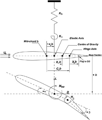
Figure 1 shows the typical wing section used to derive the structural equations of motion. This model has been well established for two-dimensional aeroelastic analysis (Dowell et al., 1994; Fung, 1955; Glaser, 1987). The degrees of freedom associated with the aerofoil are shown in Figure 1. The pitching and plunging displacements are restrained by a pair of springs attached to the elastic axis (EA) with spring constants K ? and K h, respectively. A torsional spring is also attached at the hinge axis whose spring constant is K ?.


Figure 1: Aeroelastic parameter definition

Djayapertapa (2001) and Scanlan and Rosenbaum (1951) describe the derivation of the two degrees of freedom aeroelastic equation of motion from Lagrange s equation, and the same principal can be applied to a three degree of freedom system. The resulting governing equations are given by:

(1)
(2)
(3)

where the symbol definitions are shown in Figure 1. S ? is the static moment of the aerofoil about the EA and is given by S ? = mX ? b. S ? is the static moment of the control surface about the hinge axis and is given by S ? = mX ? b. is the aerofoil moment of inertia about the EA, and is the control surface moment of inertia about the EA.

In order to obtain the full non-dimensional form of the equation, non-dimensional plunge ( ? = h/ b

UNLIMITED FREE
ACCESS
TO THE WORLD'S BEST IDEAS

SUBMIT
Already a GlobalSpec user? Log in.

This is embarrasing...

An error occurred while processing the form. Please try again in a few minutes.

Customize Your GlobalSpec Experience

Category: Gyroscopes
Finish!
Privacy Policy

This is embarrasing...

An error occurred while processing the form. Please try again in a few minutes.