Structural Steel Designer's HandBook: AISC, AASHTO, AISI, ASTM, AREMA, and ASCE-07 Design Standards, Fourth Edition

The basic design procedures that apply to bridges with straight stringers apply also to bridges with curved stringers (Arts. 12.1 to 12.4). In determination of stresses, however, the effects of curvature must be taken into account (Art. 12.5).
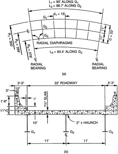
To illustrate the design procedure, a curved, two-lane highway bridge with simply supported, composite, plate-girder stringers will be designed. As indicated in the framing plan in Fig. 12.19a, the stringers are concentric and the supports and diaphragms are placed radially. Outer girder G 1 spans 90 ft and has a radius of curvature R 1 of 300 ft. Spacing of diaphragms along this span is d 1 = 15 ft. Distance between inner and outer grids G 1 and G 3 is D = 22 ft c to c, and G 2 is midway between them. The typical cross section in Fig. 12.19b shows a 22-ft-wide roadway flanked by two 3-ft 3-in-wide safety walks.
Structural steel to be used is Grade 36. Concrete to be used for the deck is Class A, with 28-day strength
. Appropriate design criteria given in Art 10.7 will be used for this structure. The approximate analysis described in Art. 12.5 for open framing will be applied to the design of the girders.
Concrete Slab. The slab is designed, to span...