Advanced PIC Microcontroller Projects in C: From USB to RTOS with the PIC18F Series

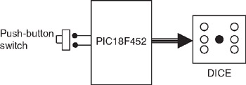
This is a simple dice project based on LEDs, a push-button switch, and a PIC18F452 microcontroller operating with a 4MHz resonator. The block diagram of the project is shown in Figure 6.6.
As shown in Figure 6.7, the LEDs are organized such that when they turn ON, they indicate numbers as on a real dice. Operation of the project is as follows: The LEDs are all OFF to indicate that the system is ready to generate a new number. Pressing the switch generates a random number between 1 and 6 which is displayed on the LEDs for 3 seconds. After 3 seconds the LEDs turn OFF again.
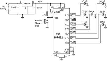
The circuit diagram of the project is shown in Figure 6.8. Seven LEDs representing the faces of a dice are connected to PORTC of a PIC18F452 microcontroller in current sourcing mode using 290-ohm current limiting resistors. A push-button switch is connected to bit 0 of PORTB (RB0) using a pull-up resistor. The microcontroller is operated from a 4MHz resonator connected between pins OSC1 and OSC2. The microcontroller is powered from a +9V battery, and a 78L05-type voltage regulator IC is used to obtain the +5V supply required for the microcontroller.
The operation of the project is described in PDL in Figure 6.9. At the beginning of the program PORTC pins are configured as outputs and...