Advanced PIC Microcontroller Projects in C: From USB to RTOS with the PIC18F Series

Keypads are small keyboards used to enter numeric or alphanumeric data into microcontroller systems. Keypads are available in a variety of sizes and styles, from 2 2 to 4 4 or even bigger.
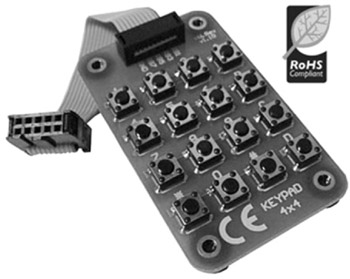
This project uses a 4 4 keypad (shown in Figure 6.43) and an LCD to design a simple calculator.
Figure 6.44 shows the structure of the keypad used in this project which consists of sixteen switches formed in a 4 4 array and named numerals 0-9, Enter, "+", ".", "-", "*", and "/". Rows and columns of the keypad are connected to PORTB of a microcontroller which scans the keypad to detect when a switch is pressed. The operation of the keypad is as follows:
A logic 1 is applied to the first column via RB0.
Port pins RB4 to RB7 are read. If the data is nonzero, a switch is pressed. If RB4 is 1, key 1 is pressed, if RB5 is 1, key 4 is pressed, if RB6 is 1, key 9 is pressed, and so on.
A logic 1 is applied to the second column via RB1.
Again, port pins RB4 to RB7 are read. If the data is nonzero, a switch is pressed. If RB4 is 1, key 2 is pressed, if RB5 is 1, key 6 is pressed, if RB6 is 1, key 0 is pressed, and so on.
This process is repeated...