Selection of Polymeric Materials: How to Select Design Properties from Different Standards

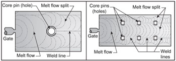
As the cooling melt front of the thermoplastic polymer enters the mold cavity and comes into contact with stationary obstacles such as core pins, the melt front is divided into two cold melt fronts, forcing the formation of weld lines as both thermoplastic melts flow around both sides of the stationary object during cavity filling.
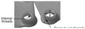
Figure 2.21 shows an internal threaded boss mounted perpendicular to a flat plate. The picture on the left is the part after molding; the boss's weld line cannot be detected. The picture on the right shows failure at the weld line, caused by the screw hoop stresses at the boss's weld line. Failure may result due to the assembly torque, or end-use application loads (temperature, creep).
Figure 2.22 shows how the weld lines are formed when the melt splits around core pins during the injection molding process.
Cross section areas containing weld lines can be significantly lower in strength than the rest of the structure. The strength of the weld line will largely depend on the lubricants compounded into the resin, properties of the material, mold design (vents and individual temperature control of the cores), spray lubricant used on the mold surface cavities, and the injection molding parameters (which control the temperatures of the melt fronts as they are reunited). A conservative estimate of weld line strength...