Handbook of Machining and Metalworking Calculations

With easy-to-use tables, charts, listings, and formulas, this convenient hands-on resource will help you solve virtually any problem involving metalworking and machining tools and applications.
A ratchet is a form of gear in which the teeth are cut for one-way operation or to transmit intermittent motion. The ratchet wheel is used widely in machinery and many mechanisms. Ratchet-wheel teeth can be either on the perimeter of a disk or on the inner edge of a ring.
The pawl, which engages the ratchet teeth, is a beam member pivoted at one end, the other end being shaped to fit the ratchet-tooth flank.
Ratchet Gear Design. In the design of ratchet gearing, the teeth must be designed so that the pawl will remain in engagement under ratchet-wheel loading. In ratchet gear systems, the pawl will either push the ratchet wheel or the ratchet wheel will push on the pawl and/or the pawl will pull the ratchet wheel or the ratchet wheel will pull on the pawl. See Figs. 8.1a and b for the four variations of ratchet and pawl action. In the figure, F indicates the origin and direction of the force and R indicates the reaction direction.
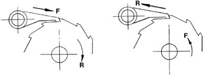

Tooth geometry for case I in Fig. 8.1a is shown in Fig. 8.2. A line perpendicular to the face of the ratchet-wheel tooth must pass between the center of the ratchet wheel...