Handbook of Machining and Metalworking Calculations
With easy-to-use tables, charts, listings, and formulas, this convenient hands-on resource will help you solve virtually any problem involving metalworking and machining tools and applications.
 TABLE OF CONTENTS
 The mechanisms and linkages discussed in this chapter have many applications for the product designer, tool engineer, and others involved in the design and manufacture of machinery, tooling, and mechanical devices and assemblies used in the industrial context. A number of important mechanical linkages are shown in Sec. 11.5, together with the mathematical calculations that govern their operation.
Mechanisms and Principles of Operation. When you study the operating principles of these devices, you will be able to see the relationships they have with the basic simple machines such as the lever, wheel and axle, inclined plane or wedge, gear wheel, and so forth. There are seven basic simple machines from which all machines and mechanisms may be constructed either singly or in combination, including the Rolomite mechanism. The hydraulic cylinder and gear wheel are also considered members of the basic simple machines.
Shown in Sec. 11.4 are other mechanisms which are used for tool-clamping purposes.
A number of practical mechanisms are shown in Sec. 11.3 together with explanations of their operation, in terms of their operational equations.
See Figs. 11.1 and 11.2.


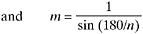
Kinematics of the External Geneva Drive. Assumed or given: a, n, d, and p.
a = crank radius of driving member
n = number of slots in drive
d = roller diameter
p = constant velocity of driving crank,...