
-
Supplier: Accuris
Description: GASKET, WAVEGUIDE FLANGE (COVER)
-
Supplier: Accuris
Description: GASKETS, WAVEGUIDE FLANGE (COVER)
-
Supplier: Accuris
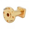
Description: FLANGES, WAVEGUIDE (COVER) (ROUND, 8 HOLE)
-
-
Supplier: Accuris
Description: FLANGE, WAVEGUIDE (COVER) (SQUARE, 4 HOLE)
-
Supplier: Fairview Microwave Inc.
Description: Waveguides from Fairview Microwave consist of coaxial adapters, bandpass filters, bends, flexible waveguide cables, waveguide gain horns, sections and terminations. Fairview waveguides are available in standard sizes from WR-430 through WR-15 depending on type of
- Component Type: Transition Adapters
-
Supplier: Fairview Microwave Inc.
Description: Waveguides from Fairview Microwave consist of coaxial adapters, bandpass filters, bends, flexible waveguide cables, waveguide gain horns, sections and terminations. Fairview waveguides are available in standard sizes from WR-430 through WR-15 depending on type of
- Component Type: Transition Adapters
-
Supplier: Fairview Microwave Inc.
Description: Waveguides from Fairview Microwave consist of coaxial adapters, bandpass filters, bends, flexible waveguide cables, waveguide gain horns, sections and terminations. Fairview waveguides are available in standard sizes from WR-430 through WR-15 depending on type of
- Component Type: Transition Adapters
-
Supplier: Fairview Microwave Inc.
Description: Waveguides from Fairview Microwave consist of coaxial adapters, bandpass filters, bends, flexible waveguide cables, waveguide gain horns, sections and terminations. Fairview waveguides are available in standard sizes from WR-430 through WR-15 depending on type of
- Component Type: Transition Adapters
-
Supplier: CSA Group
Description: IEC 60154-4:2017 specifies the dimensions of flanges for circular waveguides for use in electronic equipment. It covers requirements for flanges drilled before or after mounting on waveguides. The aim of this document is to specify for waveguide
-
Description: IEC 60154-4:2017 specifies the dimensions of flanges for circular waveguides for use in electronic equipment. It covers requirements for flanges drilled before or after mounting on waveguides. The aim of this document is to specify for waveguide
-
Description: IEC 60154-2:2016 specifies the dimensions of flanges for ordinary rectangular waveguide for use in electronic equipment. It covers requirements for flanges drilled before or after mounting on waveguides. It should be noted that for optimum electrical performance,
-
Supplier: CSA Group
Description: IEC 60154-2:2016 specifies the dimensions of flanges for ordinary rectangular waveguide for use in electronic equipment. It covers requirements for flanges drilled before or after mounting on waveguides. It should be noted that for optimum electrical performance,
-
Supplier: QuinStar Technology, Inc.
Description: QuinStar Technology’s QWC series circular-to-rectangular waveguide transitions cover the frequency range of 18 to 220 GHz in ten waveguide bands. The waveguide transitions are used to connect standard rectangular waveguide to circular waveguide with a
- Operating Frequency Range: 26.5 to 220 GHz
- Profile: Circular
- Features: Circular to Rectangular
- Component Type: Transition Adapters
-
Supplier: Advanced Technical Materials, Inc.
Description: UG Cover mating flange
- Operating Frequency Range: 10.7 to 13.25 GHz
- EIA Waveguide Size (WR): 75
- VSWR: 1.1 :1
- Insertion Loss: 0.3 dB
-
Supplier: Pasternack
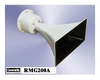
Description: PE9856-20 WR-90 standard gain horn antenna is also known as a waveguide horn. This WR-90 standard gain horn antenna has a 20 dB nominal gain and a square cover flange. Our 20 dB WR-90 horn antenna has a minimum frequency of 8.2 GHz and a maximum frequency of 12.4 GHz. WR-90
- Primary Frequency Range: 8,200 to 12,400 MHz
- Gain: 20 dB
-
Supplier: Advanced Technical Materials, Inc.
Description: Overlapping bands, custom flanges and lengths available
- Operating Frequency Range: 3.95 to 4.9 GHz
- EIA Waveguide Size (WR): 187 to 229
- VSWR: 1.05 :1
- Small Waveguide Size (WR): 187
-
Supplier: Pasternack
Description: PE9863-15 WR-284 standard gain horn antenna is also known as a waveguide horn. This WR-284 standard gain horn antenna has a 15 dB nominal gain and a square cover flange. Our 15 dB WR-284 horn antenna has a minimum frequency of 2.6 GHz and a maximum frequency of 3.95 GHz. WR-284
- Operating Frequency Range: 2.6 to 3.95 GHz
- Type: Cover or Plate
- Profile: Square
-
Supplier: ValueTronics International, Inc.
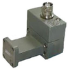
Description: to 26.5 GHz Frequency Response: ±2 dB Waveguide: WR-42 Equivalent Flange: UG-595/U SWR, <1.78 Connector: BNC Female The Agilent K422A Waveguide Crystal Detector is a convenient waveguide detector which covers the frequency range 18 to 26.6 GHz with a response of ±2
- Frequency Range: 26,500 MHz
-
Supplier: Visual Sound, Inc.
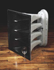
Description: long-term durability. The horn portion of the assembly is a handcrafted one-piece Patented Focused Array™ wave-guide, precision molded in hand-laminated, reinforced fiberglass for optimum performance. With substantial fiberglass layering and integral throat and driver flange construction, the
-
Supplier: Visual Sound, Inc.
Description: long-term durability. The horn portion of the assembly is a handcrafted one-piece waveguide, precision molded in hand-laminated, fiber-reinforced fiberglass for optimum performance. With substantial fiberglass layering and integral throat and driver flange construction, the horn is






Find Suppliers by Category Top
Featured Products Top
-
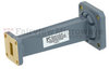
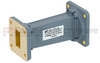
 Maury produces waveguide components in a broad range of popular waveguide sizes. A comprehensive line of standard products is available in standard EIA WR rectangular waveguide sizes. They are generally supplied with cover flanges. Units from R through P bands are normally aluminum construction (read more)
Browse RF Waveguide Components Datasheets for Maury Microwave -
configurations, which cover all common EIA flange sizes from WR650 to WR22 in 2.4mm, 2.92mm, 3.5mm, SMA, 7mm, Type N, and TNC, covering frequencies from DC to 50 GHz. These adapters feature precision indexing holes and lapped flanges to facilitate proper mating; ensuring that your connections will (read more)
Browse RF Adapters Datasheets for Maury Microwave
More Information Top
 Indicates content that may require registration and/or purchase.

-
A simple x‐band waveguide‐to‐microstrip E‐probe transition
With the microstrip line in place, the movablc backshort is connected to the grooved flange and provides excellcnt con- Figure 2 Test fixtureshowing the two grooves in the top half of the waveguide cover flange : (a) top view and (b) end view .