Frequency-to-Current Converters Information
Last revised: November 1, 2024
Reviewed by: Scott Orlosky, consulting engineer
Frequency-to-current converters are electronic circuits that produce an output current proportional or related to the frequency of an alternating current (AC) input of a specific frequency. The input signal can be of any type, as long as it is a periodic wave: for example, a sine wave, square wave, or triangular wave.
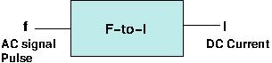
Block diagram of an F-to-C converter
Operation
There are many different F-to-C converter designs. Integrated circuits (IC) can create converters with the specific characteristics desired when combined with external components. Some of these ICs include the pervasive 555 timer, the TC9400, and the LM331. The latter two chips can be wired as voltage-to-frequency converters or as frequency-to-voltage converters. By adding components it is possible to create a circuit that is stable, accurate, and designed for a specific application.
As an example, the following circuit is a frequency-to-voltage and/or current converter. The basic internal structure of the LM331 consists of a clock generator, a voltage to frequency modulator, a voltage reference circuit, and other devices. By adding components as is shown in the following figure, an acceptable frequency-to-voltage and frequency-to-current converter can be achieved.
In this design the LM331 is wired as a single-source frequency-to-voltage converter. The input is a periodic signal that can be a square or sinusoidal wave, and the output voltage is proportional to the input frequency. The output voltage is across the load resistance (RL); the output can also be the current through this load, making this circuit a frequency-to-current converter.
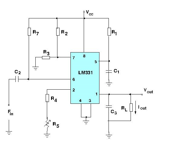
A practical F-to-C converter
Output voltage can be found using the following equation:
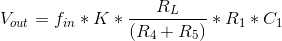
The output current equation is:

Where K is a constant and its value is dependent on the values of the external components.
Specifications
The following specifications are important to consider when selecting a frequency-to-current converters:
- Form factor:
-
- PCB. Devices are printed circuit boards (PCB) that attach to enclosures or plug directly into computer backplanes.
- Panel/chassis mounted. Devices attach to a panel or bolt onto a chassis.
- Stand alone. Devices are benchtop or floor-standing units with a full casing or cabinet, and an integral interface.
- DIN rail. Devices are mounted on a standard DIN rail. DIN is an acronym for Deutsches Institut für Normung (DIN), a German national organization for standardization.
- Rack mount. Devices are rack-mounted and fit inside enclosures such as a standard 19” telecommunications rack.
- Other Factors to Consider
- Maximum input frequency, the highest frequency the converter will accept.
- Resolution refers to the value of the Least Significant Bit (LSB) of the digital word representing the analog value. A 10-bit number contains 210, or 1024, increments. A 0-10 V signal could therefore be resolved into approximately (10/1024) ~ 0.01 V increments. A 12-bit representation would be 212 (4096) increments, or divisions of 0.002 V for the same signal. Each additional bit doubles the resolution, and one bit is required for the polarity (sign) of a number.
- Operating temperature, the full required range of ambient operating temperature.
Applications
Some applications for frequency-to-current converters are:
- Switching applications, including converters, power supplies, and motor control devices.
- Voltage conversion: to convert the voltage of an incoming signal, the frequency-to-current converter includes a transformer to provide the galvanic isolation necessary between the input signal and the output signal.
- Converting power from one standard or level to another.
- Controlling AC motor speed and torque.
- General motor control, typically using a three-phase voltage inverter in which the phases are controlled using semiconductor switches and pulse width modulation devices.
- Monitoring the speed of heavy equipment such as turbines or flow meters, or machinery used in hazardous environments, such as the underground pulley systems and conveyors used in transportation and mining. Heavy-duty frequency-to-current converters used for these applications typically have an input frequency range from 0.5 to 700 Hz and an output range from 4 to 20 mA DC.
- Producing the current for standard 4-20 mA loop circuit monitors. The 4-20 mA loop is widely used in process automation applications because it is reliable, inexpensive, and resistant to electrical noise.
Frequency-to-Current Converters FAQs
What is the typical output range of an F/I converter?
The output current is usually in the standard industrial range of 4-20 mA. This range is used to represent the full scale of the frequency input, where 4 mA typically corresponds to the minimum frequency and 20 mA to the maximum frequency.
What are the advantages of using frequency-to-current converters?
- Noise immunity: Current signals are less susceptible to noise over long distances compared to voltage signals.
- Simplicity: They provide a direct, linear conversion from frequency to current.
- Standardization: The 4-20 mA current loop is widely used in industrial applications.
- Robustness: Suitable for harsh environments, where frequency inputs can be noisy or difficult to read directly.
What types of sensors can be used with frequency-to-current converters?
F/I converters can work with sensors that output frequency signals, such as:
- Flow sensors (turbine meters, paddle wheels)
- Tachometers
- Encoders
- Proximity sensors (inductive, capacitive, optical)
- Hall effect sensors
What is the relationship between input frequency and output current?
The relationship is typically linear. For instance, if an F/I converter is configured to output 4 mA at 0 Hz and 20 mA at 1000 Hz, then an input frequency of 500 Hz would correspond to an output current of 12 mA.
Can the range of an F/I converter be adjusted?
Most F/I converters allow configuration or scaling of the input frequency range and corresponding current output range, either through manual switches, jumpers, or software settings.
How do users choose the right frequency-to-current converter?
When selecting an F/I converter, consider the following:
- Input frequency range: Ensure the converter can handle the minimum and maximum frequencies of your application.
- Output current range: Verify that the output matches the required current range, typically 4-20 mA.
- Accuracy and linearity: Check the specifications for accuracy and linearity of conversion.
- Environmental conditions: Ensure that the converter can operate under the environmental conditions of your application (temperature, humidity, etc.).
- Power supply: Check whether the converter requires an external power source or can operate in a loop-powered configuration.
What is a loop-powered F/I converter?
A loop-powered frequency-to-current converter draws power from the same current loop that it is driving. This allows for simpler wiring since only two wires are needed for both power and signal transmission.
Can an F/I converter work with noisy frequency signals?
Most F/I converters are designed to work with noisy signals by implementing filtering techniques, such as hysteresis or signal conditioning, to minimize the impact of noise.
What is the difference between a frequency-to-current converter and a frequency-to-voltage converter?
Frequency-to-current converters output a current (typically 4-20 mA), while frequency-to-voltage converters output a voltage (typically 0-5V or 0-10V). Current outputs are generally preferred in industrial applications due to better noise immunity over long distances.
Can users convert the current output back to a frequency signal?
A current-to-frequency (I/F) converter can be used to convert the 4-20 mA current back into a corresponding frequency signal. However, this adds complexity to the system.
What are common calibration techniques for F/I converters?
Calibration usually involves inputting known frequency signals and adjusting the output current to match expected values. It also involves using external calibration tools or the built-in features of the converter to fine-tune the response for accurate conversion.
Frequency-to-Current Converters Media Gallery
Introduction to Frequency Converters
References
GlobalSpec—Voltage-to-Frequency Converters
GlobalSpec—Frequency-to-Voltage Converters
Image credits: