Semiconductor Wire and Wedge Bonders Information
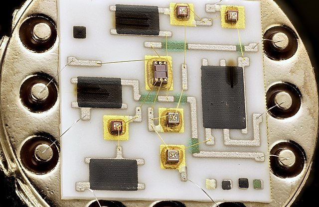
Figure 1: LH0033CG Buffer Amplifier. Source: Mister rf/CC BY-SA 4.0
For the billions of integrated circuits (ICs) produced each year, semiconductor wire and wedge bonders are critical for electrically connecting ICs to their chip carriers. Semiconductor wire and wedge bonders are used to bond extremely small wires to the tiny pads of ICs in a high precision manner. The speed and precision of wedge bonders coupled with improvements in semiconductor wire material have helped the industry continue to grow while increasing the reliability of semiconductor parts.
Theory of Operation
Semiconductor wire and wedge bonders are essential tools used in the microelectronics industry for connecting ICs or other semiconductor devices to their packaging or substrates. They create electrical connections through the process of wire bonding, which involves attaching a thin metal wire between two contact points, typically by using ultrasonic, thermosonic, or thermocompression techniques.
Wire Bonders
Wire bonders are designed to create connections using a thin metal wire, often made of gold, aluminum, or copper. The most common wire bonding techniques are ball bonding and wedge bonding.
In ball bonding, ultrasonic energy and heat are used to create a ball-shaped bond between the wire and the first bond point (usually the IC). The wire is then extended to the second bond point (usually the substrate or package) and another ultrasonic bond is formed. The wire is then cut, and the process is repeated for other connections.
For wedge bonding, the wire is clamped between two wedge-shaped tools and ultrasonic energy is applied to create a bond between the wire and the bond points. The wire is then extended and bonded to the second bond point. Wedge bonding is often used for aluminum wires or other materials that don't easily form balls.
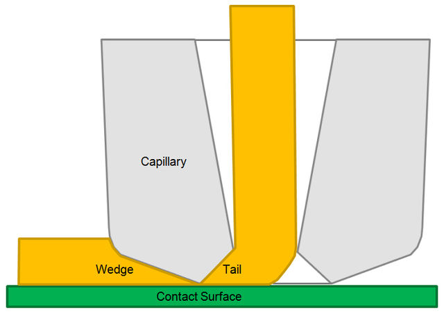
Figure 2: Sectional view of bonding capillary to show wedge- and tailbond. Source: Georg1001/CC BY-SA 3.0
Wedge Bonders
Wedge bonders are a specific type of wire bonder that uses the wedge bonding technique. The main components of a wedge bonder are:
- Bonding head
- Wire clamp
- Ultrasonic transducer
- Bonding stage
The bonding head holds the wedge tool and wire clamp, and it moves in precise patterns to create the bonds. The wire clamp holds the wire in place during the bonding process. The ultrasonic energy that is applied to the wire during the bonding process is generated by the ultrasonic transducer. Finally, the bonding stage holds the semiconductor device and substrate in place during bonding.
Wedge bonder operation is fairly straightforward but happens very quickly with high repeatability and precision. The bonding head picks up the wire and positions it over the first bond point. The ultrasonic transducer applies energy to the wedge tool, creating a bond between the wire and the bond point. The bonding head moves to the second bond point and repeats the process. The wire is cut, and the bonding head moves to the next connection.
Wedge bonders use semiconductor wire to create strong, stable electrical connections in semiconductors. Their high precision and repeatability are critical due to the number of semiconductors being produced.
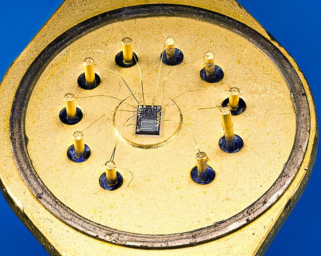
Figure 3: Close-up pic of μA791KC. Source: Mister rf/CC BY-SA 4.0
Specifications
Specifications for semiconductor wire and wedge bonders are very important. Using the wrong semiconductor wire or wedge bonder can result in poor performance or reliability of the semiconductor over time. Some of the most important specifications to be aware of are:
Bonding Wire Material and Diameter
Wire bonders can work with various wire materials, such as gold, aluminum, and copper. These wire materials come in different levels of purity and can have other elements or compounds mixed in. The wire diameter is typically specified in micrometers (µm) and can range from 17 µm to over 50 µm. Wire also comes on various spool sizes so it is important to choose a spool size that the wedge bonder can accept.
Bonding Force
This is the force applied during the bonding process, typically measured in grams (g). The appropriate bonding force depends on the wire material, diameter, and the bonding technique used. Wedge bonders allow for force adjustment but it is good to know the range of forces available.
Ultrasonic Power
The power of the ultrasonic transducer is an important specification, typically measured in watts (W). Higher power can lead to stronger and more reliable bonds, but it's important to choose the appropriate power for the specific wire material and bonding technique.
Bonding Speed
The bonding speed, usually measured in bonds per second (bps) or bonds per minute (bpm), indicates how quickly the machine can create connections. Faster bonding speeds can increase productivity but may also require more skilled operators to ensure quality.
Bonding Accuracy
The bonding accuracy, typically measured in micrometers (µm), indicates the precision with which the machine can position the wire and create bonds. Higher accuracy is essential for creating reliable connections, especially in densely packed or small-scale devices.
Bonding Techniques
Some bonders can support multiple bonding techniques, such as ball bonding and wedge bonding, while others are dedicated to one specific technique.
Substrate Size and Compatibility
The bonder should be compatible with the size and type of substrates or packages in use, such as lead frames, printed circuit boards (PCBs), or ceramic substrates.
Automation and Control
Modern wire and wedge bonders may offer automated features like programmable bonding patterns, vision systems for alignment and inspection, and software for process monitoring and data collection.
Footprint and Ergonomics
The physical size of the bonder and its compatibility with the production environment are important considerations. Additionally, consider the machine's ergonomics for operators, such as ease of use, accessibility, and safety features.
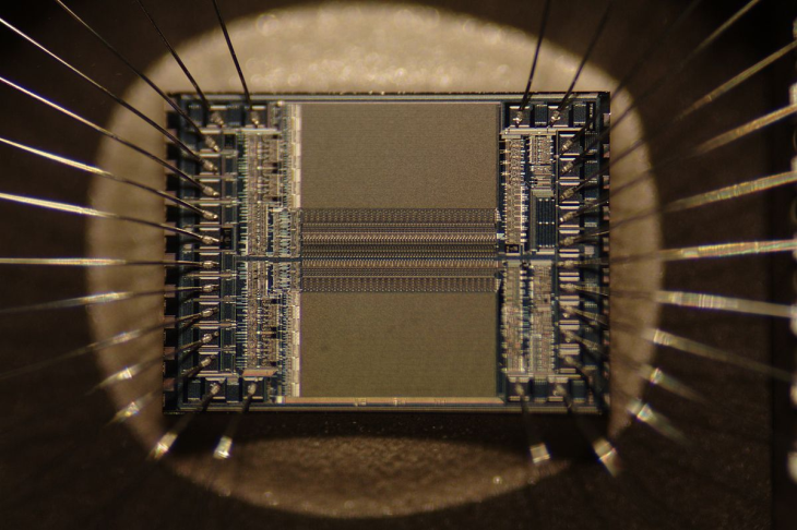
Figure 4: An EPROM microchip die showing the detail of the integrated circuit itself and the silver wires, which connect the die to legs of the chip. Source: Zephyris/CC BY-SA 3.0
Types
There are several types of semiconductor wire and wedge bonders, each designed for specific bonding techniques and applications. The primary types of bonders include:
Ball Bonders
Ball bonders are designed for the ball bonding technique, which is the most common wire bonding method. They typically use gold, copper, or silver wires and form a ball-shaped bond at one end of the wire using a combination of heat and ultrasonic energy. Ball bonders are widely used in the microelectronics industry for their high speed, fine pitch capabilities, and strong bond reliability.
Wedge Bonders
Wedge bonders use the wedge bonding technique, which involves clamping the wire between two wedge-shaped tools and applying ultrasonic energy to form the bond. Wedge bonders are often used with aluminum wires, as well as other materials that don't easily form balls. They can create strong, reliable bonds and are often used in applications that require a lower profile bond, such as power devices or high-frequency applications.
Heavy Wire Bonders
Heavy wire bonders are designed for bonding larger diameter wires, typically in the range of 100 µm to 500 µm. They are used for high-power, high-current applications, such as automotive electronics or power modules. Heavy wire bonders may use ball bonding or wedge bonding techniques, depending on the wire material and application requirements.
Ribbon Bonders
Ribbon bonders are used for bonding flat, ribbon-shaped wires, which can offer advantages in thermal performance and current-carrying capacity compared to round wires. Ribbon bonders typically use the wedge bonding technique and are often employed in high-power, high-temperature applications, such as power electronics or optoelectronic devices.
Fine Pitch Bonders
These bonders are designed for applications with very small bond pad pitches, typically less than 50 µm. Fine pitch bonders may use ball or wedge bonding techniques, depending on the application requirements, and are often employed in advanced microelectronics or high-density packaging.
Features
Semiconductor wire and wedge bonders come with a variety of features to enhance their performance, reliability, and ease of use. These features can vary depending on the manufacturer and specific model, but some common features include:
Programmable Bonding Patterns
Modern bonders often include software that allows you to program and store custom bonding patterns. Optimized bonding patterns can help streamline the bonding process and improve productivity and quality.
Vision Systems
Many bonders incorporate vision systems to assist in alignment, inspection, and process monitoring. These systems can help to ensure proper placement of bonds and identify any defects or issues with the bonding process.
Multi-Axis Motion Control
Advanced bonders typically feature precise multi-axis motion control systems, allowing for accurate positioning of the bonding head and wire during the bonding process.
Auto Wire Threading
Threading the small diameter semiconductor wire through the wedge tool can be quite difficult. This feature enables the bonder to automatically thread the wire through the capillary or wedge tool, which can save time and reduce the potential for operator error.
Adjustable Bonding Force and Ultrasonic Power
Many bonders allow users to adjust the bonding force and ultrasonic power to optimize the bonding process for different wire materials, diameters, and techniques. Some bonders allow the operator to control parameters for the initial bond and the second bond independently.
Touchscreen Interface
A user-friendly touchscreen interface can make it easier for operators to interact with the bonder, input settings, and monitor the bonding process.
Process Monitoring and Data Collection
Some bonders include built-in monitoring and data collection capabilities, which can help users track key process parameters, analyze the performance of the bonder, and implement process improvements.
Automatic Wire Clamping and Cutting
Many bonders feature automatic wire clamping and cutting mechanisms, which can help to ensure consistent wire lengths and clean cuts, improving the overall quality and reliability of the bonds.
Heated Work Stage
Some bonders include a heated work stage, which can help to improve bond quality and reliability, especially when working with temperature-sensitive materials or processes like thermosonic or thermocompression bonding.
Compatibility with Different Wire Materials and Diameters
Advanced bonders may be designed to work with a variety of wire materials (such as gold, aluminum, or copper) and diameters, offering flexibility in bonding applications. Semiconductor wire also comes on different spool sizes so it is important to understand which sizes the machine can accept.
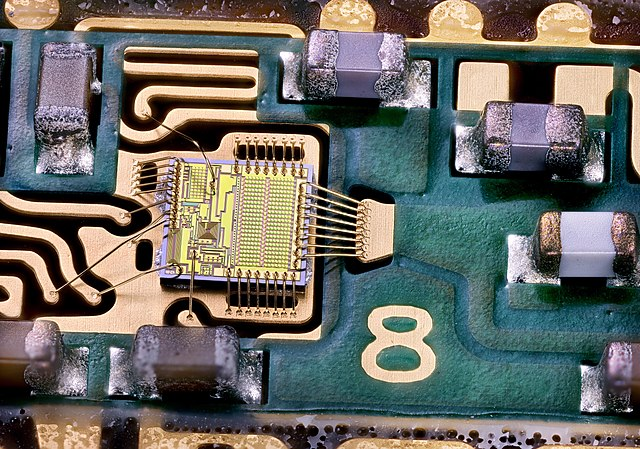
Figure 5: Agilent RF Power Amplifier QCPM8893. Source: Mister rf/CC BY-SA 4.0
Manufacture
The manufacturing process of wedge bonders involves several steps, including design, component selection, assembly, testing, and quality control. While the specific processes may vary among manufacturers and models, the general approach can be summarized as follows:
Once the design is finalized, the manufacturer selects appropriate components for the bonder. These components can include motors and actuators for precise movement, ultrasonic transducers, sensors, cameras for vision systems, and control systems for managing the bonding process. The manufacturer may source these components from external suppliers or produce them in-house.
The bonder's components are then assembled to create the final machine. This can involve assembling the mechanical structure, installing motors and actuators, connecting the electronics and control systems, and integrating the software. Assembly requires skilled technicians and strict quality control measures to ensure the proper functioning and reliability of the bonder.
Once assembled, the bonder undergoes testing and calibration to ensure it meets the specified performance criteria. This can include tests for accuracy, bonding force, ultrasonic power, and bonding speed. The bonder may also be tested with various wire materials and bonding techniques to ensure its compatibility and performance across different applications.
Throughout the manufacturing process, strict quality control measures are implemented to ensure the reliability and performance of the bonder. This can include inspecting incoming components, monitoring the assembly process, and conducting final inspections of the completed machine. Quality control measures help to minimize defects and ensure the bonder performs as expected in the field.
The manufacturing process of wedge bonders requires a combination of skilled engineering, precision assembly, and stringent quality control measures to meet the demands of these precision machines. By following these steps, manufacturers can produce bonders that meet the demands of the microelectronics industry and provide reliable, high-quality connections for a wide range of semiconductor devices.
Applications
Semiconductor wire and wedge bonders play a critical role in the microelectronics industry by creating electrical connections between integrated circuits, semiconductor devices, and their packaging or substrates. The applications for wire and wedge bonders are vast and span across various industries that rely on electronic devices. Some of the key applications include:
- Consumer electronics
- Automotive electronics
- Power electronics
- Telecommunications
- Medical devices
- IoT (internet of things) devices
- MEMS (Microelectromechanical systems)
Wire and wedge bonders are used to create connections in various consumer electronic devices such as smartphones, tablets, laptops, and wearable devices. These devices often require high-density, fine-pitch connections to accommodate their compact form factors and advanced functionality.
Modern vehicles are equipped with numerous electronic systems for engine control, safety, infotainment, and more. Wire and wedge bonders are used to create connections in automotive electronic components, such as engine control units (ECUs), airbag control modules, and advanced driver assistance systems (ADAS).
Wire and wedge bonders are essential in the production of power devices such as power modules, inverters, converters, and power supplies. These devices often require heavy wire or ribbon bonding to handle high current and thermal demands.
The telecommunications industry relies on wire and wedge bonders for manufacturing RF (radio frequency) and microwave devices, including amplifiers, filters, and antennas. These devices often require wedge bonding due to their high-frequency performance requirements.
Wire and wedge bonders are used in the production of various medical devices, such as implantable cardiac pacemakers, hearing aids, and medical imaging equipment. These applications often demand high-reliability connections and biocompatible materials.
Wire and wedge bonders are crucial for manufacturing IoT devices, which require compact, low-power, and high-density connections. Examples include smart sensors, home automation systems, and industrial control systems.
Wire and wedge bonders play a role in the manufacturing of MEMS devices, which combine mechanical and electrical components on a microscopic scale. Examples of MEMS devices include accelerometers, gyroscopes, and pressure sensors.
These are just a few examples of the many applications for semiconductor wire and wedge bonders. The demand for reliable, high-quality electrical connections in various industries will continue to drive the need for advanced wire and wedge bonding technologies.
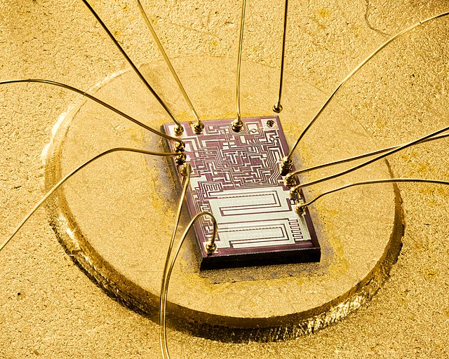
Figure 6: Close-up pic of μA791KC. Source: Mister rf/CC BY-SA 4.0
Standards
Various industry standards and guidelines apply to semiconductor wire and wedge bonders to ensure quality, reliability, and consistency in the bonding process. Some of the key standards and organizations involved in developing these guidelines include:
JEDEC (Joint Electron Device Engineering Council)
JEDEC is a leading organization that develops standards and guidelines for the microelectronics industry. They have several standards related to wire bonding, such as JESD22-B116 (Wire Bond Shear Test) and JESD22-B113 (Ball Bond Pull Test), which define test procedures for evaluating the strength and reliability of wire bonds.
SEMI (Semiconductor Equipment and Materials International)
SEMI is a global industry association that represents the semiconductor equipment, materials, and manufacturing sectors. They develop various standards and guidelines that apply to semiconductor manufacturing equipment, including wire and wedge bonders. Some relevant standards include SEMI E10 (Specification for Definition and Measurement of Equipment Reliability, Availability, and Maintainability) and SEMI E89 (Guide for Measurement System Analysis).
IPC (Association Connecting Electronics Industries)
IPC is an international organization that develops standards and guidelines for the electronics assembly and production industries. They have several standards related to wire bonding, such as IPC-A-610 (Acceptability of Electronic Assemblies), which includes criteria for evaluating the quality and reliability of wire bonds in electronic assemblies.
ASTM International (American Society for Testing and Materials)
ASTM is a global organization that develops and publishes technical standards for various materials, products, and services. They have several standards related to wire bonding, such as ASTM F458 (Standard Test Method for Heat Resistance of Wire Bonds) and ASTM F459 (Standard Test Method for Measuring Pull Strength of Wire Bonds).
These standards and organizations play a crucial role in ensuring the quality, reliability, and consistency of wire and wedge bonding processes in the semiconductor industry. Manufacturers of wire and wedge bonders must adhere to these standards and guidelines to meet industry requirements and provide reliable, high-quality equipment for their customers.